Getting Started with the FRDM Automotive S32K312 Development Board for General Purpose
本文档内容
-
Out of the Box
-
Get Software
-
Plug It In
-
Build, Run
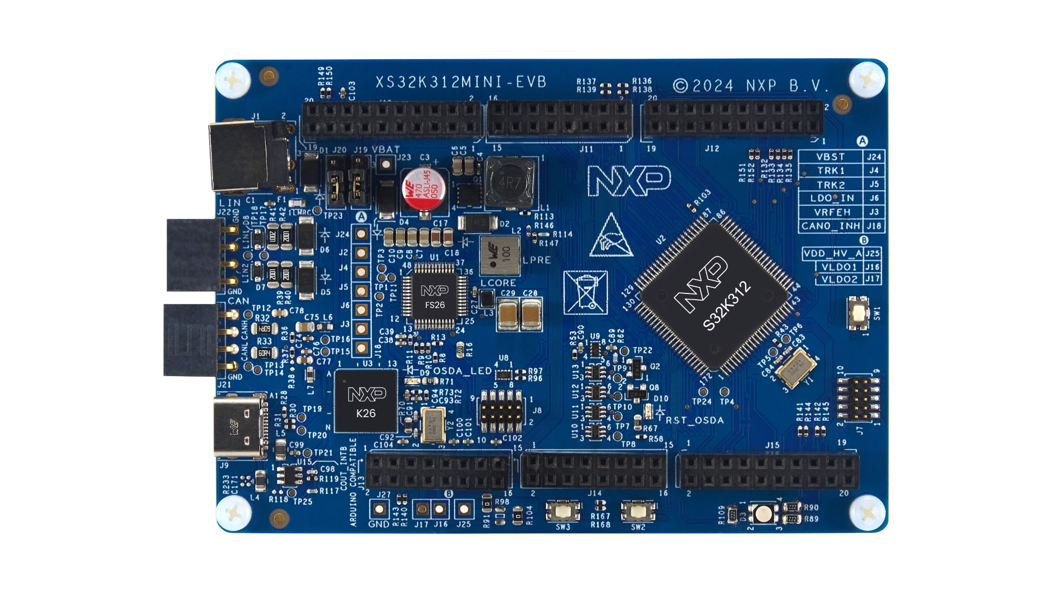
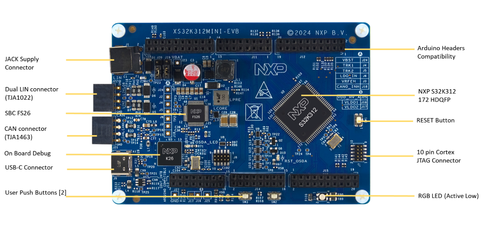
1. Out of the Box
1.1 Get to Know the FRDM-A-S32K312 Development Board

2. Get Software
Sign in at NXP with your credentials.
2.1 Install Software
- Go to the software bundle using the following link S32K3 FRDM Automation Bundle
- Click Generate to download
- Run the NXP Multi Installer
- Launch S32 Design Studio for S32 Platform 3.6.5 from the shortcut that has been created on your desktop
By selecting “Launch executable after download” and “Installation and configuration without any interaction” the FRDM Bundle will be installed alongside all its available components.
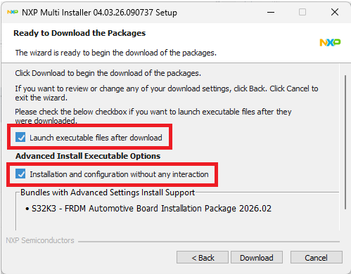
All the Software and Tools are now installed and configured automatically.
3. Plug It In
3.1 Plug in the Power Supply
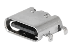
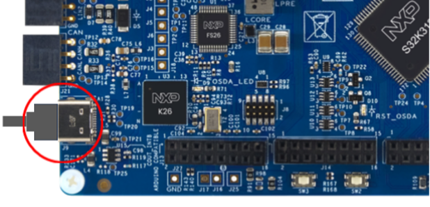
The first method to provide power is via J9 USB-C connector (this board does not include power delivery), but the current will be limited to 500 mA (this to enable for Desktops with USB-A or USB-C connector), so this supplying method is only recommended for low-demand current applications. Even in this supplying method Controller Area Network (CAN) or Local Interconnect Network Physical Layer (LIN PHY) (Is not recommended to use both PHYs at maximum current demand at the same time) can work because the FS26 enable a boost circuit to supply the +12.0 V voltage refences of the PHYs.

The maximum current demand for +12.0 V in this supplying method is 170 mA due to the boost circuit consumption. To supply the board with the above descripted methodology, follow the steps descripted in the Table 5.
3.2 Start-up Sequence
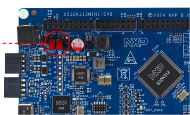
Ensure that the jumpers J19 and J20 are placed in the position 1 - 2 in order to power supply via the USB-C connector (J9).
Plug in the USB-C sire to the J9 connector.
4. Build, Run
4.1 Build, Run
To accelerate your development, visit the Application Code Hub.
There you can:
- Access a wide range of validated application examples
- Download ready to use software for rapid prototyping
- Work with tested code assets that follow current design guidelines and best practices
Design Resources
Board Resources
Chip Documents
Software
- S32K3 Standard Software Package
- S32K3 Reference Software Package
- S32 Design Studio IDE
- Real-Time Drivers (RTD)
- S32K Power Estimation Tool (PET)
- Model-Based Design Toolbox (MBDT)
- Structural Core Self-Test (SCST) Library
- FreeMASTER Run-Time Debugging Tool
- Inter-Platform Communication Framework (IPCF)
- Automotive Math and Motor Control Library (AMMCLib)
- S32 Safety Software Framework (SAF) and Safety Peripheral Drivers (SPD)
Support
Forums
Connect with other engineers and get expert advice on designing with the FRDM-A-S32K312 Development Board using our community sites.