Getting Started with MR-MCXN-T1
本文档内容
-
Out of the Box
-
Get to Know the Hardware
-
Build, Run
-
Plug It In
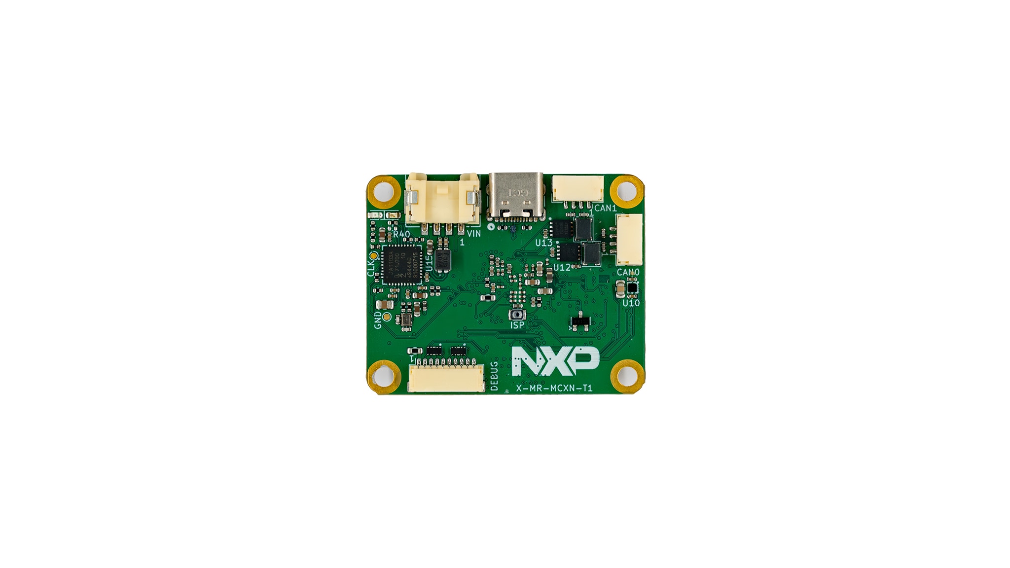
1. Out of the Box
The MR-MCXN-T1 Hub is the sensor and I/O node reference design of the NXP Mobile Robotics family. It is a networked node built around an NXP MCXN947 microcontroller that aggregates sensors and distributes them over automotive 100BASE-T1 Ethernet and CAN FD, acting as a distributed sensor/I/O hub in a time-sensitive networking (TSN) robotics system. This guide shows how to download or build the firmware and flash it, so the node is ready to run. It covers the MR-MCXN-T1-OFLO, MR-MCXN-T1-GNSS and MR-MCXN-T1-IO shield variants.
Detailed documentation of the MR-MCXN-T1-Hub is here: NXP Robotic Platforms Documentation .
1.1 Kit Contents
- MR-MCXN-T1 base board based on the NXP MCXN947 microcontroller
- 10-pin SH debug cable (Pixhawk Debug Full 10) between the MCU-Link-MR and the board debug port
- One or more example shield variants are ordered and purchased separately to be paired with the base board, also called a hub (OFLO optical-flow, F9P GNSS or I/O expander)
1.2 Additional Hardware Required
- USB-C cable into the board's native USB-C connector for power
- MCU-Link-MR debug probe for flash/debug and the serial console
1.3 Minimum System Requirements (Optional)
A Linux host PC is required to run the SDK toolchain. Downloading and building images are done inside a Docker container built from the SDK Dockerfile, so Docker must be installed and the host must have outbound network access.
- Linux host PC (Ubuntu 24.04 recommended) with Docker installed
- At least 25 GB of free disk space on the Docker storage volume
- Outbound internet access to fetch the SDK containers and artifacts
- A USB port for the debug/flash probe and board power
1.4 Software
Install the following software before working with this board. The SDK orchestrates image download and build; the flashing tool programs the board.
- NXP Robotic Platforms SDK (west-based) run inside the SDK Docker container
- west meta-tool and Docker on the Linux host
- NXP LinkServer (MCU-Link-MR) to flash the MCUboot bootloader and the signed application
- A serial terminal (screen/minicom/tio/picocom) for the CDC-ACM console
2. Get to Know the Hardware
The MR-MCXN-T1 Hub is a validated node design that customers can evaluate, reproduce and extend with their own shields.
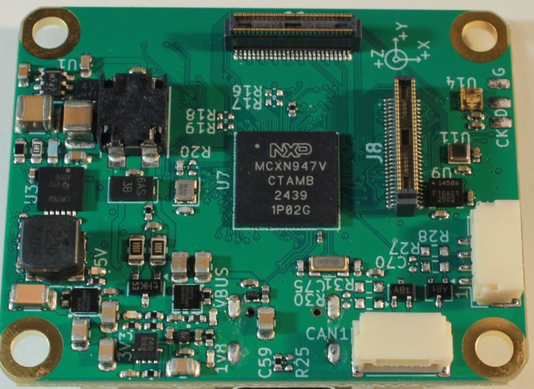
2.1 Board Features
- NXP MCXN947 Arm Cortex-M33 microcontroller with integrated analog and communication peripherals
- Runs Zephyr RTOS or the Cerebri (CogniPilot) ROS 2 stack
- Bridges onboard sensors to the robotics network over 100BASE-T1 Ethernet and CAN FD
- Two DF40TC board-to-board connectors for shields
2.2 Board Description
The MCXN947 is an NXP Arm Cortex-M33 microcontroller with integrated analog and communication peripherals. It runs Zephyr RTOS or the Cerebri (CogniPilot) ROS 2 stack and bridges onboard sensors to the robotics network through its Ethernet and CAN FD interfaces.
2.3 Board Components
The reference design integrates the following main NXP components and interfaces:
- MCXN947 microcontroller (Arm Cortex-M33)
- 3.3 V and 1.8 V regulation from a 3S to 12S input through NXP NX5P3363 load switches and a DC-DC regulator
- ICM-45686 inertial sensor, BMM350 magnetometer and BMP581 barometer
- 100BASE-T1 automotive Ethernet through the NXP TJA1103 PHY
- Two CAN FD channels through NXP TJA1462 transceivers
- USB 2.0, addressable RGB LED and an SWD/console debug connector
- Two DF40TC board-to-board connectors exposing FlexComm, FlexIO, ADC, comparator, DAC, SAI, PDM and FlexPWM for shields
3. Build, Run
This section explains how to obtain MR-MCXN-T1 firmware, prebuilt or built from source, and how to flash it with NXP LinkServer. It applies to both Zephyr and Cerebri (CogniPilot) stacks. Two application stacks are available, both built via west sdk build --stack:
| Stack | --stack |
What It Is? | Typical Use |
|---|---|---|---|
| Zephyr | Zephyr (default) | Stock Zephyr samples for this board | Peripheral bring-up and validation |
| Cerebri (CogniPilot) | Cerebri | CogniPilot ROS 2/zenoh sensor-node apps | Running the board as a robotics sensor node |
3.1 Download or Build the Images
The images are either downloaded prebuilt or built from source with the SDK. Both commands run inside the SDK Docker container. Prebuilt artifacts are the fastest way to get started.
Download the prebuilt artifacts:
west sdk download --platform mr-mcxn-t1Or build them from source:
west sdk build --platform mr-mcxn-t1Artifacts land in <west topdir>/bin/mr-mcxn-t1/, next to the robotics-sdk clone. Run west sdk list for the authoritative platform list. The SDK downloads or builds images but does not flash them; deployment is done with the board's native tool.
Each Cerebri app maps to a specific shield, and the SDK injects the matching shield overlay automatically, so --shield is not passed:
| App | Implied Shield |
|---|---|
optical_flow |
oflo (optical-flow shield) |
gnss |
f9p (u-blox F9P GNSS shield) |
io_exp |
io_exp (I/O expander) |
Build a specific Cerebri app from source, for example:
west sdk build --platform mr-mcxn-t1 --stack cerebri optical_flowwest sdk build --platform mr-mcxn-t1 --stack cerebri (all Cerebri apps)3.2 What to Flash
Every MR-MCXN-T1 example is a sysbuild build producing two images. The bootloader is typically programmed once; during normal development only the application image needs to be updated.
| Image | Collected As | Absolute Flash Address |
|---|---|---|
| MCUboot Bootloader | mcuboot.bin |
0x10000000 (flash base, boot_partition, 80 kB) |
| Signed Application | zephyr.signed.bin |
0x10014000 (flash base + slot0 offset 0x14000) |
Collected copies appear under bin/mr-mcxn-t1/<stack>/<shield>/<example>/ as mcuboot.bin and zephyr.signed.bin. Flash the signed application (zephyr.signed.bin) at the slot0 address 0x10014000, not the raw zephyr.bin at flash base. MCUboot lives at flash base and chainloads the signed app in slot0.
3.3 Flash with LinkServer
Install LinkServer and confirm it is visible by running LinkServer -v. Then flash the two images:
- Flash the bootloader
- Flash the signed app into
slot0 - Watch the MCU-Link-MR console for serial output
LinkServer flash MCXN947 load --addr 0x10000000 mcuboot.binLinkServer flash MCXN947 load --addr 0x10014000 zephyr.signed.binscreen /dev/ttyACM0 115200 (or minicom/tio/picocom)MCUboot boots, validates the slot0 image and chainloads it; sample output appears on the CDC-ACM console.
Two potential issues:
- J-Link's connector does not fit some MR-MCXN-T1 units, use MCU-Link + LinkServer
- LinkServer flash has no remote mode, so run it on the host physically wired to the board
4. Plug It In
4.1 Plug It In
Connect the following before deployment:
- MR-MCXN-T1 base board with the shield variant (OFLO, GNSS or I/O) mounted
- USB-C cable into the board's native USB-C connector for power
- MCU-Link-MR for flash/debug and power; it enumerates as
/dev/ttyACM0(Linux/macOS) or MCU-Link VCom Port (COM*) on Windows - 10-pin SH debug cable from the MCU-Link-MR (Pixhawk Debug Full 10) to the board debug port
Design Resources
Board Information
Support
Forums
Connect with other engineers and get expert advice on designing with the MR-MCXN-T1 using our community sites.