Getting Started with MCXW236B-CLICK Board
本文档内容
-
Plug It In
-
Get Software
-
Build and Run
-
MCUXpresso Developer Experience
1. Plug It In
Let's take your MCXW236B-CLICK board for a test drive. In the following steps, you may either watch the sequence in a short video, or following the detailed actions listed below.
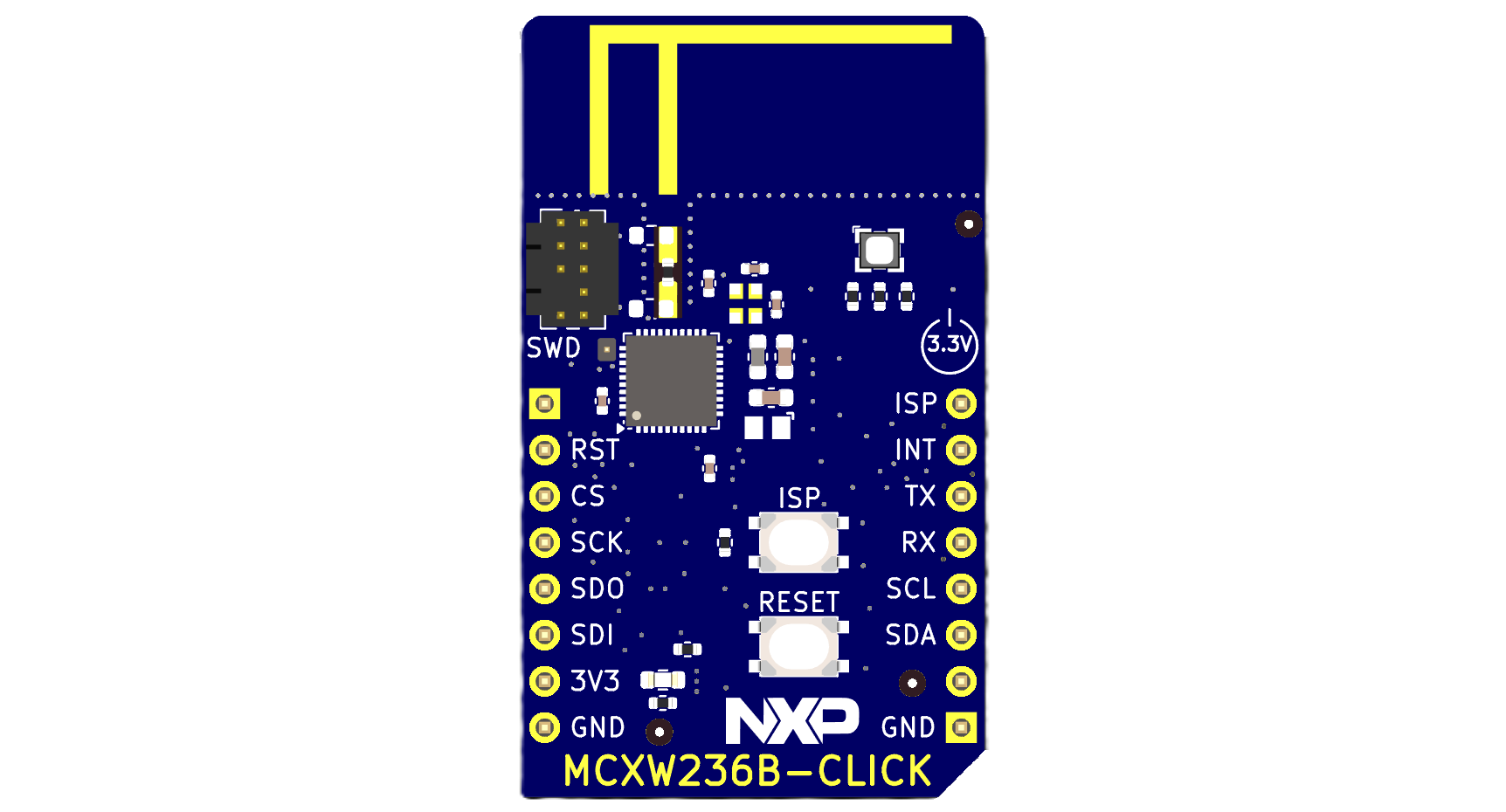
1.1 Get Familiar with the Board
The MCXW236B-CLICK board comes preloaded with the ble_fsci_black_box demo, which is designed to establish communication between boards and unlock the full potential of the MCXW23 through command-based interaction.

1.2 Set Up the Board
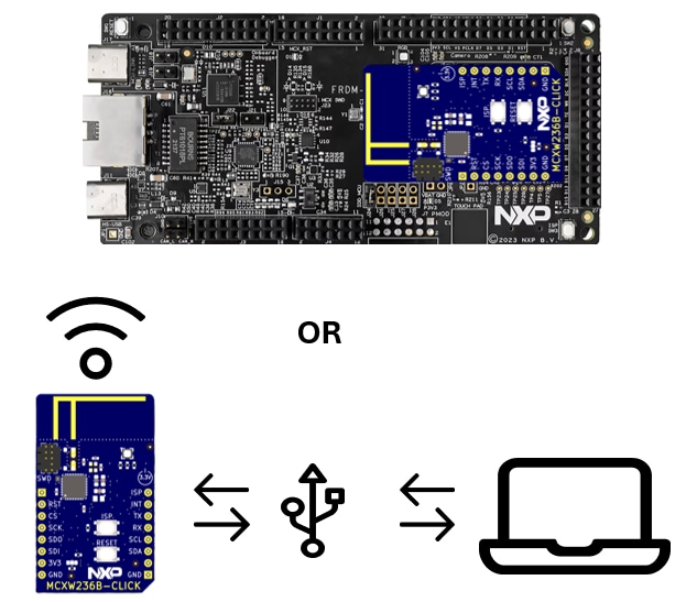
There are two main ways to enable and use the MCXW236B-CLICK board:
- Using a USB-to-serial converter, connect the MCXW236B-CLICK board to a USB-to-universal asynchronous receiver-transmitter (UART) device and send commands via the NXP Test Tool
- Using a host board with a MikroE connector, connect the MCXW236B-CLICK to a compatible NXP development board (for example, FRDM-MCXN947, FRDM-MCXC444) and use it as a network coprocessor
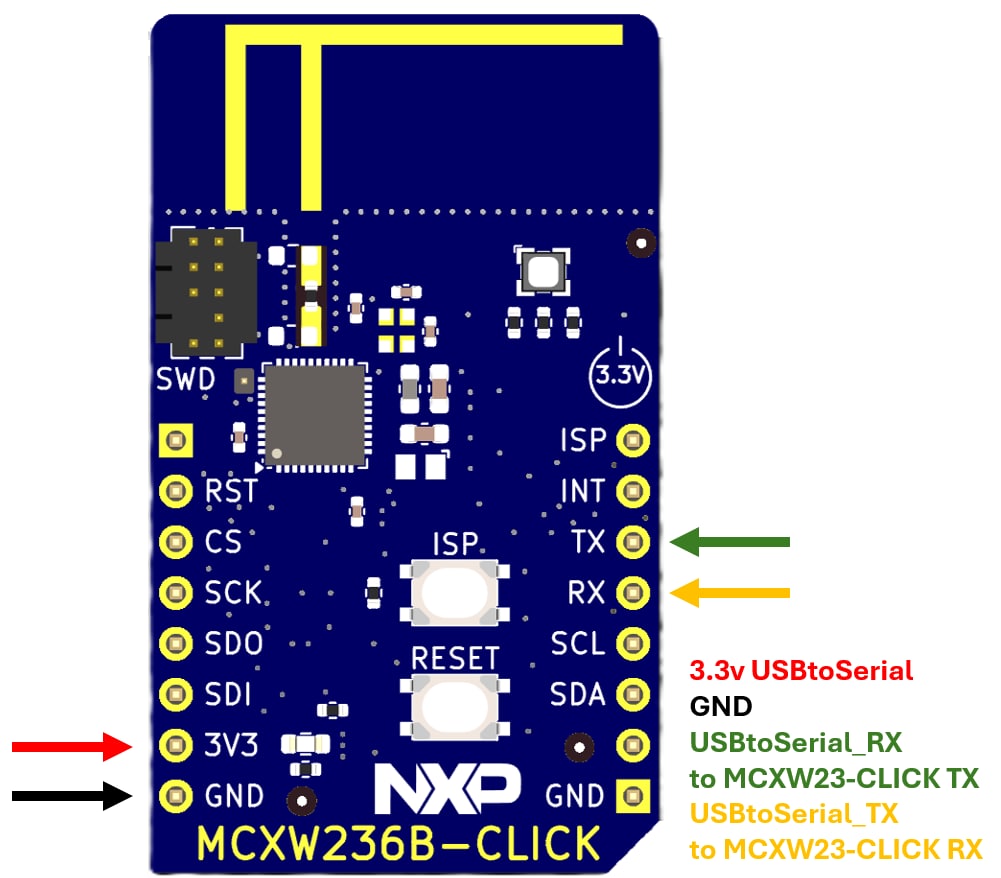
USB-to-UART Wiring Instructions:
- Connect
J4pin 6 (TXD_FC2_URTA) of the MCXW236B-CLICK to the RX pin of the USB-to-UART converter - Connect
J4pin 5 (RXD_FC2_URTA) to the TX pin of the converter - Connect
J4pin 1 (GND) to the GND of the converter - Connect
J5pin 7 (3.3 V) to the 3.3 V output of the USB converter
1.3 Plug in the Board
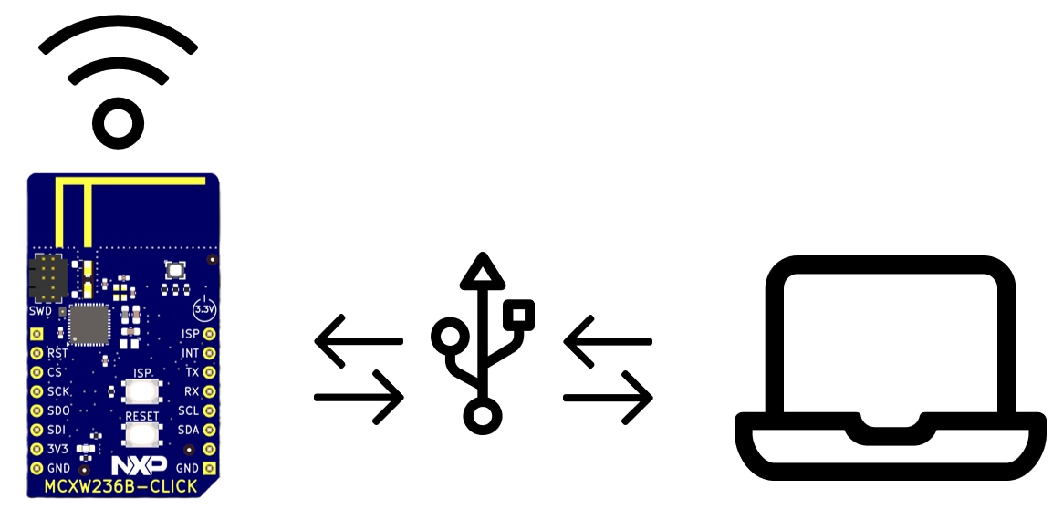
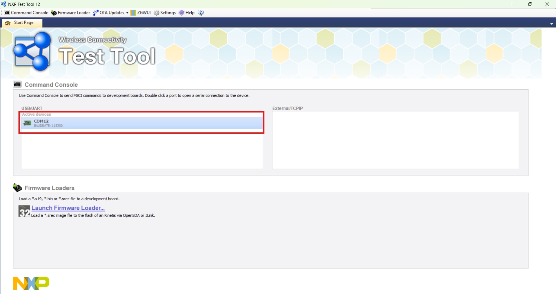
Connect the MCXW236B-CLICK board to a host computer using a USB-to-Serial converter.
Open the NXP TestTool app, connect to the board using the correct COM port. Load the example.xml (from the Run section) and run the macros.
2. Get Software
2.1 Install the NXP's TestTool
Connectivity tools are a collection of applications that communicate with the NXP development boards via a serial interface. They assist in the development and testing process of either 802.15.4 MAC, Simple MAC (SMAC), Thread, Bluetooth® Low Energy (BLE), Matter or Zigbee 3.0 based applications.
To communicate and enable MCXW23 BLE functionality, you will be using the NXP Test Tool from the connectivity tool suite, which is a graphical user interface (GUI)-based utility that communicates via serial interface to the NXP development boards and is made up of a set of different applications:
- Command Console is used to send various commands to an NXP board
- Firmware Loader that can download new firmware onto an NXP board removed from Test Tool versions above 12.9.2.2
- Supports Media Access Control (MAC), Thread and BLE protocols through over-the-air (OTA) updates of the board firmware
Zigbee® Gateway Graphical User Interface (ZGWUI) is an application developed to allow an easy setup of a ZigBee network and run without a need for any special knowledge.
2.2 Heart Rate Sensor
The .xml file used in the NXP Test Tool serves as a macro script that automates the sending of framework serial communication interface (FSCI) commands to a connected NXP device.
Here you can find an .xml file that serves as an example to set up the MCXW236B-CLICK boards, the Test Tool sends each command from the XML to the microcontroller unit (MCU) using the FSCI protocol and the MCU receives the commands and processes them using its BLE stack.
For the Heart Rate Sensor demo, the commands:
- Initialize the BLE stack
- Dynamically build the generic attribute profile (GATT) database (including the Heart Rate Service and its characteristics)
- Set advertising parameters
- Start advertising
- Optionally send beats per minute (BPM) notifications
<?xml version="1.0"?>
<ZigBee>
    <Settings>
        <DefaultCmds>
            <MacroScript>
                <MacroName>New Macro Script</MacroName>
				<MacroCmd>FSCI-CPUReset.Request</MacroCmd>
				<MacroCmd>Delay 1000</MacroCmd>
				<MacroCmd>GATT-Init.Request</MacroCmd>
				<MacroCmd>Delay 1000</MacroCmd>
				<MacroCmd>GATTServer-RegisterCallback.Request</MacroCmd>
				<MacroCmd>Delay 1000</MacroCmd>
				<MacroCmd>GATTDBDynamic-AddPrimaryServiceDeclaration.Request 0000 01 1801</MacroCmd>
				<MacroCmd>Delay 1000</MacroCmd>
				<MacroCmd>GATTDBDynamic-AddCharacteristicDeclarationAndValue.Request 01 2A05 02 0004 0004 00000000 00</MacroCmd>
				<MacroCmd>Delay 1000</MacroCmd>
				<MacroCmd>GATTDBDynamic-AddCccd.Request</MacroCmd>
				<MacroCmd>Delay 1000</MacroCmd>
				<MacroCmd>GATTDBDynamic-AddPrimaryServiceDeclaration.Request 0000 01 1800</MacroCmd>
				<MacroCmd>Delay 1000</MacroCmd>
				<MacroCmd>GATTDBDynamic-AddCharacteristicDeclarationAndValue.Request 01 2A00 02 000B 000B 4E58505F424C455F485253 01</MacroCmd>
				<MacroCmd>Delay 1000</MacroCmd>
				<MacroCmd>GATTDBDynamic-AddCharacteristicDeclarationAndValue.Request 01 2A01 02 0002 0002 4003 01</MacroCmd>
				<MacroCmd>Delay 1000</MacroCmd>
				<MacroCmd>GATTDBDynamic-AddCharacteristicDeclarationAndValue.Request 01 2A04 02 0008 0008 0A0010006400E204 01</MacroCmd>
				<MacroCmd>Delay 1000</MacroCmd>
				<MacroCmd>GATTDBDynamic-AddPrimaryServiceDeclaration.Request 0000 01 180D</MacroCmd>
				<MacroCmd>Delay 1000</MacroCmd>
				<MacroCmd>GATTDBDynamic-AddCharacteristicDeclarationAndValue.Request 01 2A37 10 0016 0002 00B4 00</MacroCmd>
				<MacroCmd>Delay 1000</MacroCmd>
				<MacroCmd>GATTDBDynamic-AddCccd.Request</MacroCmd>
				<MacroCmd>Delay 1000</MacroCmd>
				<MacroCmd>GATTDBDynamic-AddCharacteristicDeclarationAndValue.Request 01 2A38 02 0001 0001 01 01</MacroCmd>
				<MacroCmd>Delay 1000</MacroCmd>
				<MacroCmd>GATTDBDynamic-AddCharacteristicDeclarationAndValue.Request 01 2A39 08 0001 0001 00 10</MacroCmd>
				<MacroCmd>Delay 1000</MacroCmd>
				<MacroCmd>GATTDBDynamic-AddPrimaryServiceDeclaration.Request 0000 01 180F</MacroCmd>
				<MacroCmd>Delay 1000</MacroCmd>
				<MacroCmd>GATTDBDynamic-AddCharacteristicDeclarationAndValue.Request 01 2A19 02 0001 0001 5A 01</MacroCmd>
				<MacroCmd>Delay 1000</MacroCmd>
				<MacroCmd>GATTDBDynamic-AddCharacteristicDescriptor.Request 01 2904 0007 0400AD27010100 01</MacroCmd>
				<MacroCmd>Delay 1000</MacroCmd>
				<MacroCmd>GATTDBDynamic-AddCccd.Request</MacroCmd>
				<MacroCmd>Delay 1000</MacroCmd>
				<MacroCmd>GATTDBDynamic-AddPrimaryServiceDeclaration.Request 0000 01 180A</MacroCmd>
				<MacroCmd>Delay 1000</MacroCmd>
				<MacroCmd>GATTDBDynamic-AddCharacteristicDeclarationAndValue.Request 01 2A29 02 0003 0003 4E5850 01</MacroCmd>
				<MacroCmd>Delay 1000</MacroCmd>
				<MacroCmd>GATTDBDynamic-AddCharacteristicDeclarationAndValue.Request 01 2A24 02 0008 0008 4852532044656D6F 01</MacroCmd>
				<MacroCmd>Delay 1000</MacroCmd>
				<MacroCmd>GATTDBDynamic-AddCharacteristicDeclarationAndValue.Request 01 2A25 02 0007 0007 424C45534E3031 01</MacroCmd>
				<MacroCmd>Delay 1000</MacroCmd>
				<MacroCmd>GATTDBDynamic-AddCharacteristicDeclarationAndValue.Request 01 2A27 02 0008 0008 4D43585732330000 01</MacroCmd>
				<MacroCmd>Delay 1000</MacroCmd>
				<MacroCmd>GATTDBDynamic-AddCharacteristicDeclarationAndValue.Request 01 2A26 02 0005 0005 312E312E31 01</MacroCmd>
				<MacroCmd>Delay 1000</MacroCmd>
				<MacroCmd>GATTDBDynamic-AddCharacteristicDeclarationAndValue.Request 01 2A28 02 0005 0005 312E312E34 01</MacroCmd>
				<MacroCmd>Delay 1000</MacroCmd>
				<MacroCmd>GATTDBDynamic-AddCharacteristicDeclarationAndValue.Request 01 2A23 02 0008 0008 000000FEFF9F0400 01</MacroCmd>
				<MacroCmd>Delay 1000</MacroCmd>
				<MacroCmd>GATTDBDynamic-AddCharacteristicDeclarationAndValue.Request 01 2A2A 02 0004 0004 00000000 01</MacroCmd>
				<MacroCmd>Delay 1000</MacroCmd>
				<MacroCmd>GAP-SetAdvertisingParameters.Request 0800 0800 00 00 00 000000000000 07 00</MacroCmd>
				<MacroCmd>Delay 1000</MacroCmd>
				<MacroCmd>GAP-SetAdvertisingData.Request 01 03 01 01 06 02 02 0D18 07 08 4E58505F485253 00</MacroCmd>
				<MacroCmd>Delay 1000</MacroCmd>
				<MacroCmd>GAP-StartAdvertising.Request</MacroCmd>
            </MacroScript>
        </DefaultCmds>
    </Settings>
</ZigBee>3. Build and Run
Using the framework serial communication interface (FSCI) with an microcontroller unit (MCU) enables developers to control and test wireless protocols like Bluetooth® Low Energy (BLE) without writing embedded code.
The Test Tool sends FSCI commands (defined in an .xml macro file) over a serial interface (typically UART or USB) to an MCU running a compatible firmware such as ble_fsci_black_box. These commands initialize the BLE stack, build the generic attribute profile (GATT) database (including services like Heart Rate), configure advertising and send runtime data like beats per minute (BPM) values.
The MCU interprets these commands and responds accordingly, allowing a BLE client (for example, the NXP IoT Toolbox app) to connect and receive notifications. This setup is ideal for rapid prototyping, debugging and validating BLE behavior using a PC-hosted interface. Developers can use another MCU (for example, an NXP board with a MikroE connector) to send FSCI commands programmatically over universal asynchronous receiver transmitter (UART), enabling the creation of custom host applications that control the BLE stack externally. This setup is ideal for rapid prototyping, debugging and building network coprocessor (NCP) solutions where the BLE logic is offloaded to a dedicated wireless MCU.
3.1 Run Hearth Rate Sensor
Run the heart rate sensor using the MCXW236B-CLICK board, an USB-to-serial converter and the NXP test tool.
- Follow the steps in the Set up the boards section to connect the MCXW236B-CLICK board to a USB-to-serial Converter
- Open the NXP's TestTool
- Connect to your board by selecting the correct COM port
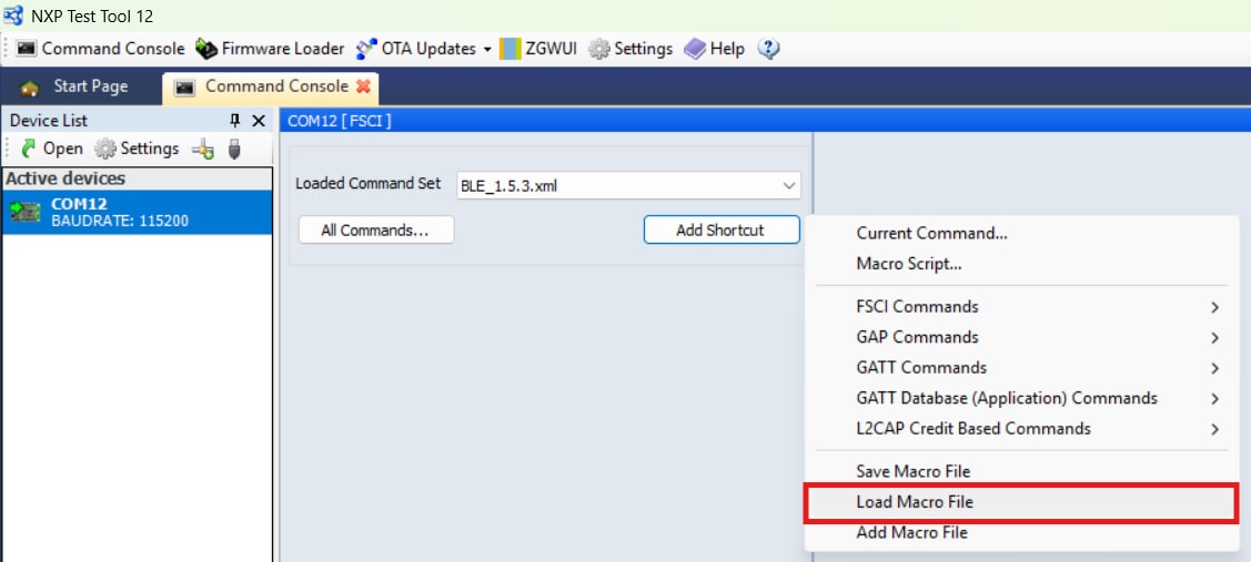
- Set the "Loaded Command Set" to BLE_1.5.3.xml
- Load the "BLE_HRS_MCXW23_Demo.xml.xml" script from the get the software version into the tool by clicking on the "Add shortcut" button and then click the load macro file button
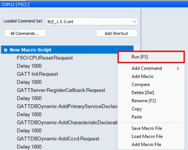
- Run the Macro script by right-clicking the "New Macro Script tab" and click "Run"
- Commands will be transmitted sequentially via the communication interface and displayed in the right panel of the companion application, along with the corresponding responses received from the board
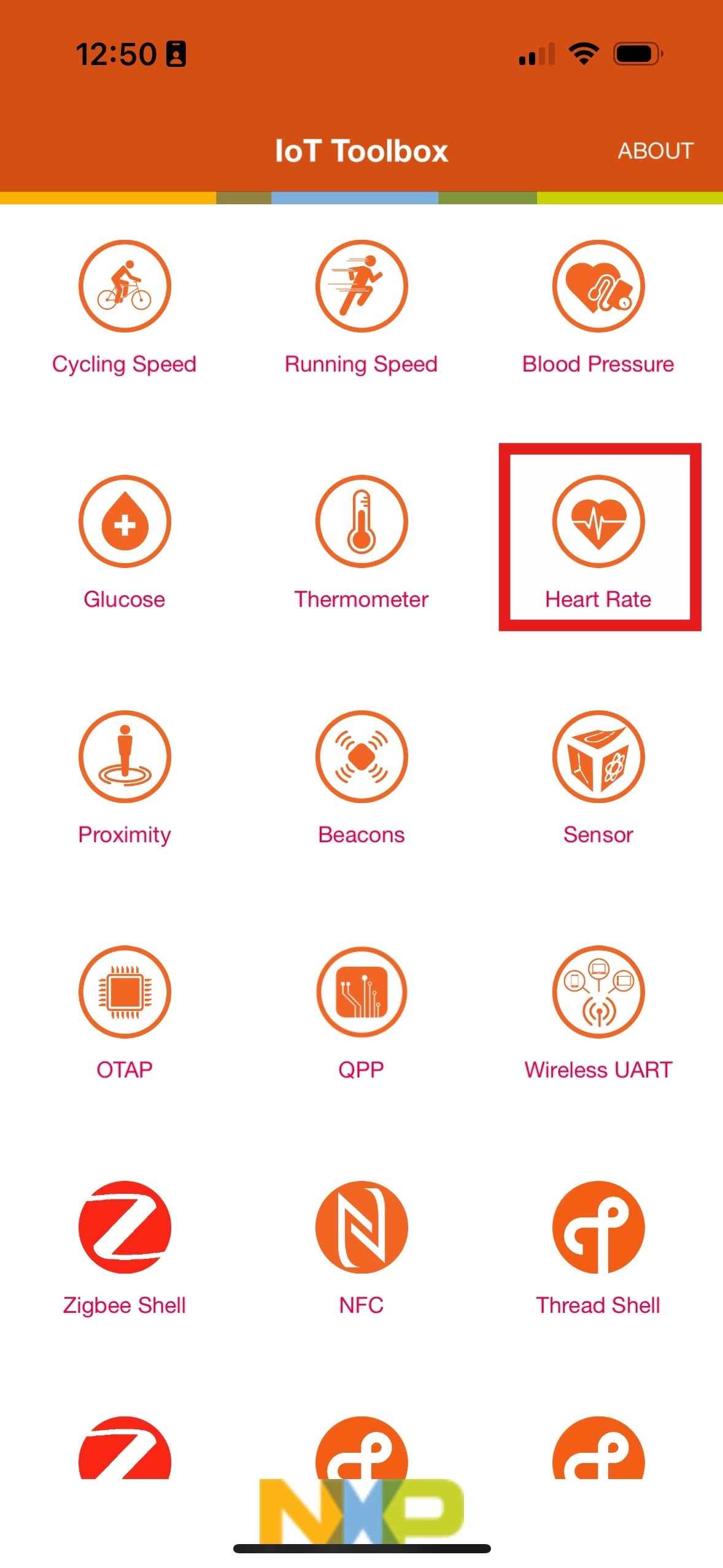
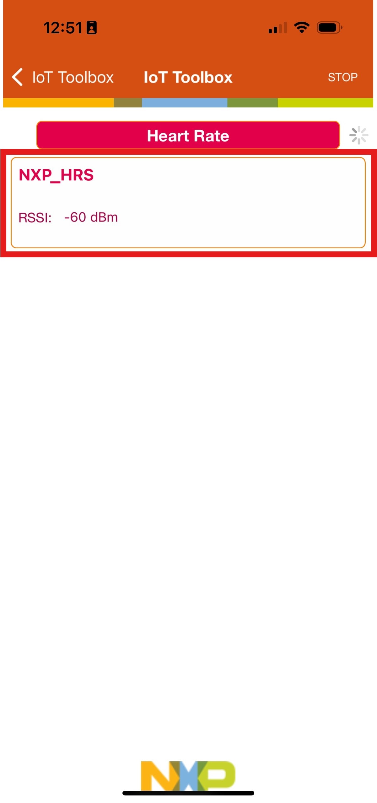
- Open the NXP IoT Toolbox App and click the Heart Rate icon
- Wait for the "NXP_HRS" device to show on the screen and select it
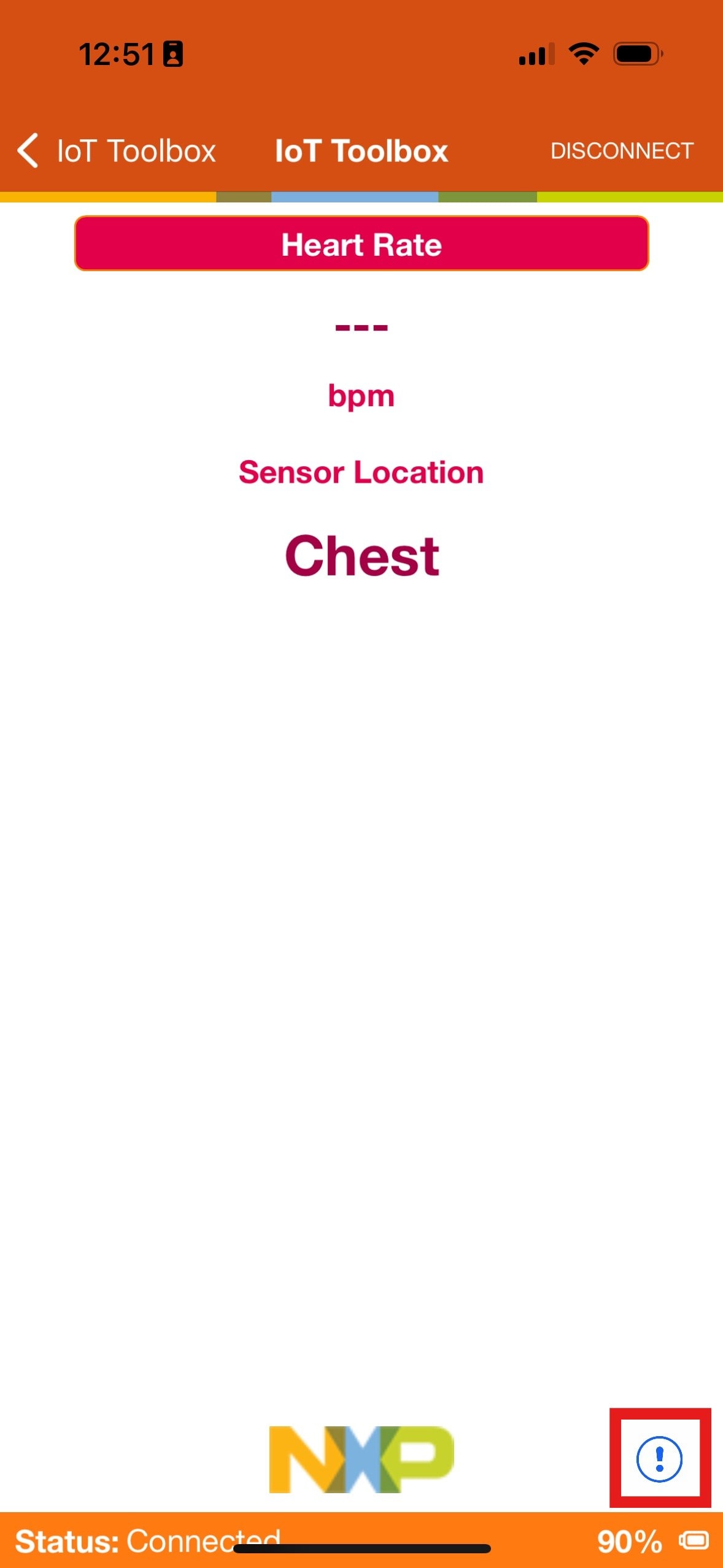
- After the connection is established, the screen will show the following details:
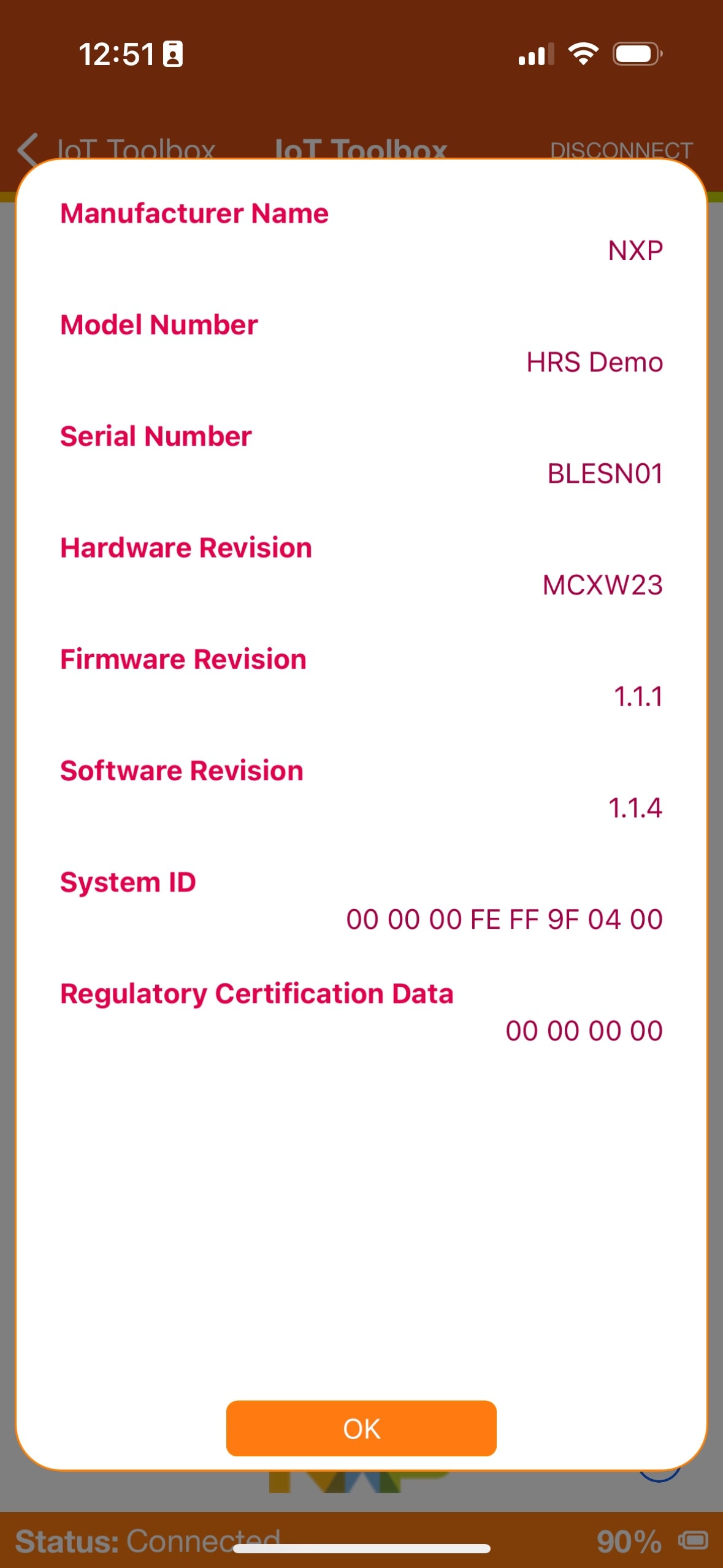
- Click the "!" icon to show extra information on the demo

5. MCUXpresso Developer Experience
Check out each of the following sections to learn about the ecosystem provided for flexible protyping and development. In the video below, we will introduce you to the FRDM platform, the full-featured EVK and the compatible shields for extended capabilities. In addition we will walk you through our Application Code Hub portal where we provide numerous application examples through NXP's Github.
4.1 FRDM Platform, Full Feature EVK and Shields
For quick prototyping platforms, we offer both the low-cost FRDM platform and the full-featured EVK.
FRDM development boards come with standard form factor and headers, easy access to MCU I/Os, on-board MCU-Link debugger and a USB-C cable. Our full featured evaluation kits include extended I/O and interface access, extendibility with WiFi and additional MCU-Link features. There are also many compatible Click Boards and/or Arduino shields. For those that are supported with an Open CMSIS Pack examples may be available on ACH, but if not, many of them are easy to use via serial interface like I²C, SPI and UART, for which we provide drivers with examples in the MCUXpresso SDK.
4.2 Application Code Hub
The Application Code Hub further enhances our MCUXpresso Developer Experience by giving developers an interactive dashboard to quickly locate software. Visit the ACH today to start exploring or discover additional details and benefits of the new interactive Application Code Hub.
Software accessible from Application Code Hub is located in NXP’s GitHub repository so it can be easily accessed and cloned from that location directly.
4.3 Demo Walkthrough
The following demo walks us through importing a project from ACH using a system based on the FRDM platform with a motor control shield and a low cost LCD. Although your evaluation board may differ from this system, the following steps can be replicated and used for all supported platforms.