远程I/O平台(RIOP)快速入门
1. 开箱即用
恩智浦远程I/O平台(RIOP)通过提供灵活、高精度的数据采集和安全的多协议连接,加速工业自动化进程,适用于工厂和流程控制系统。该平台旨在简化与工业4.0环境的集成,支持预测性维护,并为客户优化了可靠性与运营效率。
1.1 套件内含物/装箱单
该套件内含物包括:
- 完成组装和测试的评估板,放在防静电袋中
- USB Micro-B线
- 24V电源适配器
- 3根彩色导线
1.2 其他硬件
除套件内含物外,请自备一根以太网线。
1.3 最低系统要求
运行评估板需要满足以下配置的Windows PC工作站:
- Windows 10及更高版本操作系统
- 可用的以太网端口或一个USB转以太网适配器
1.4 软件与工具前提条件
使用本评估板必须安装以下软件。评估板的信息页上提供了所有必要的软件。
- 下载并安装FreeMASTER 3.2
- 在我们的应用代码中心(ACH) 和GitHub页面下载并解压随附的源代码
2. 安装和设置软件(SW)
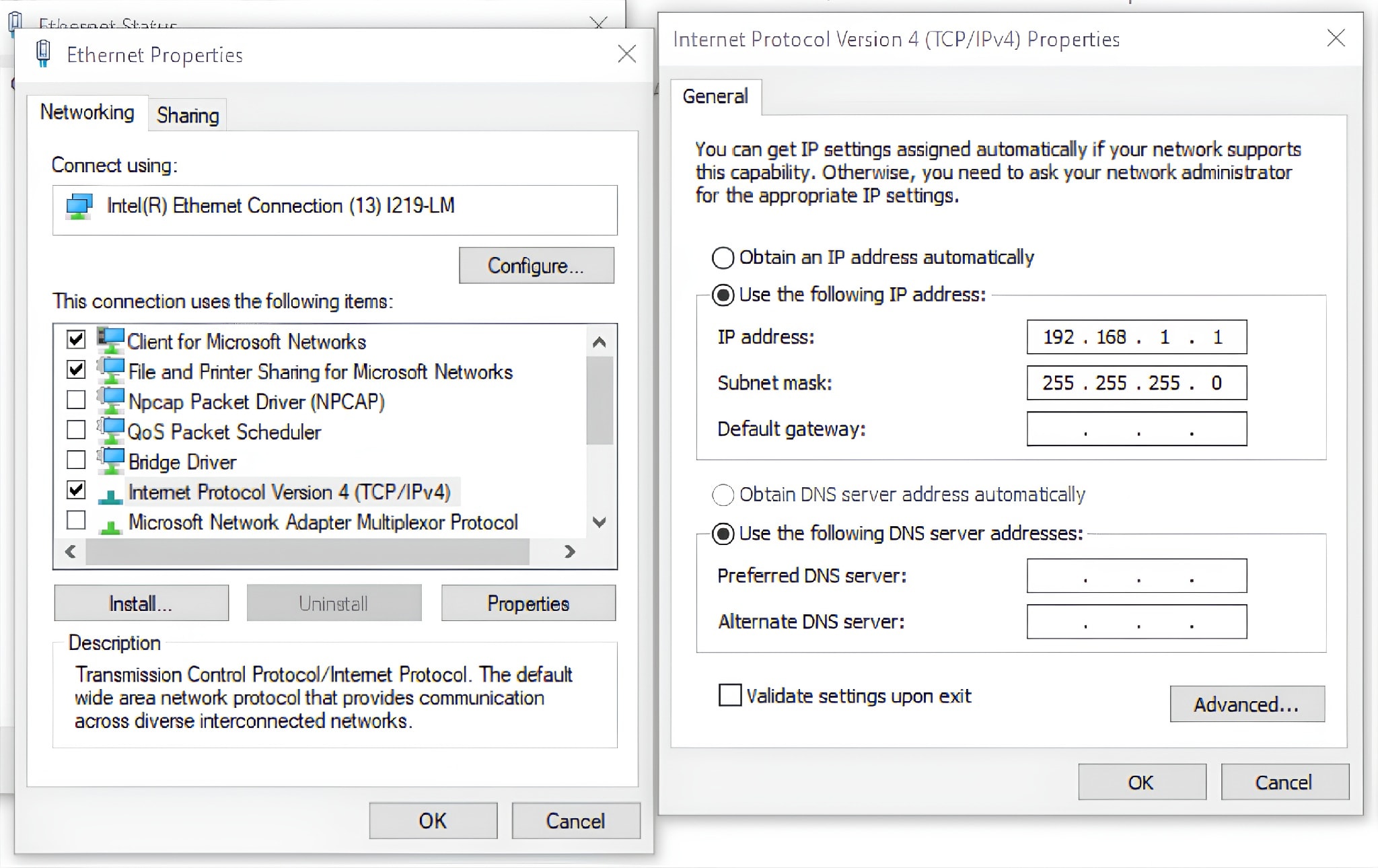
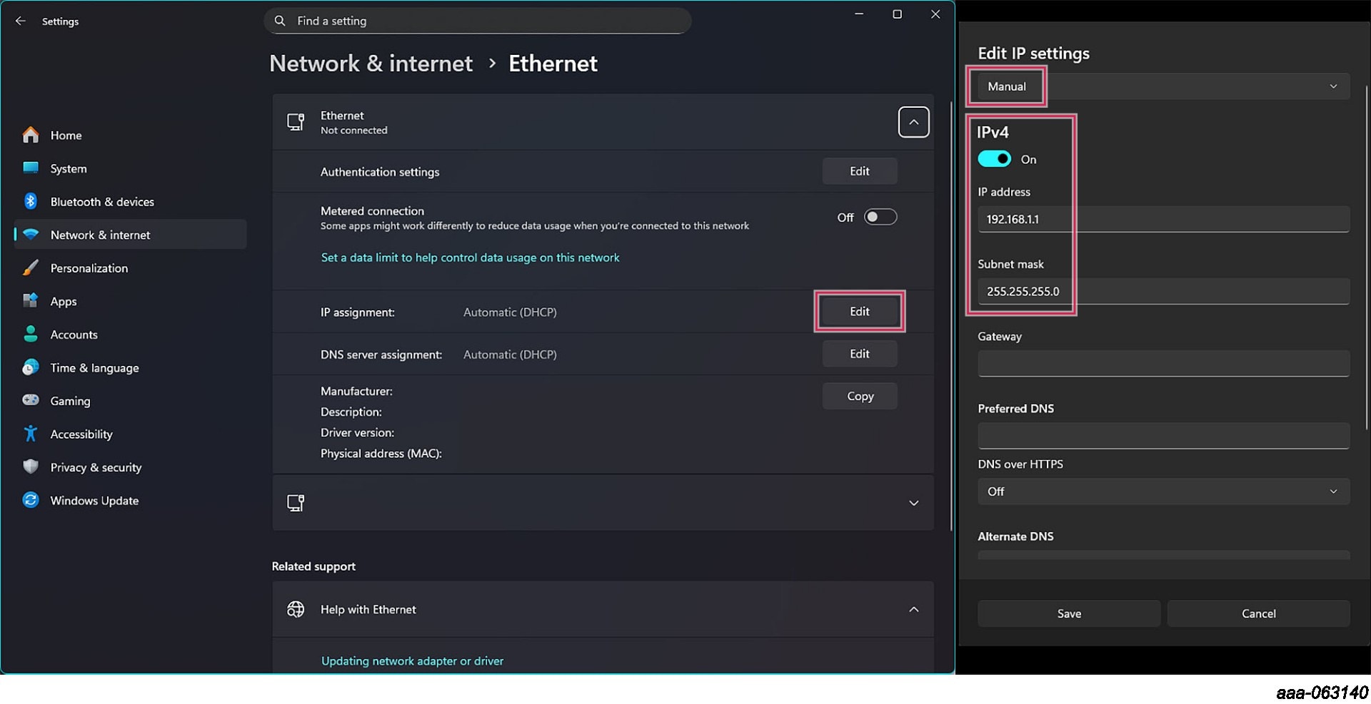
该套件预装了一个开箱即用的演示应用。要运行它,需要配置一个以太网端口(按照本章节说明)并安装FreeMASTER 3.2。
3. 硬件介绍
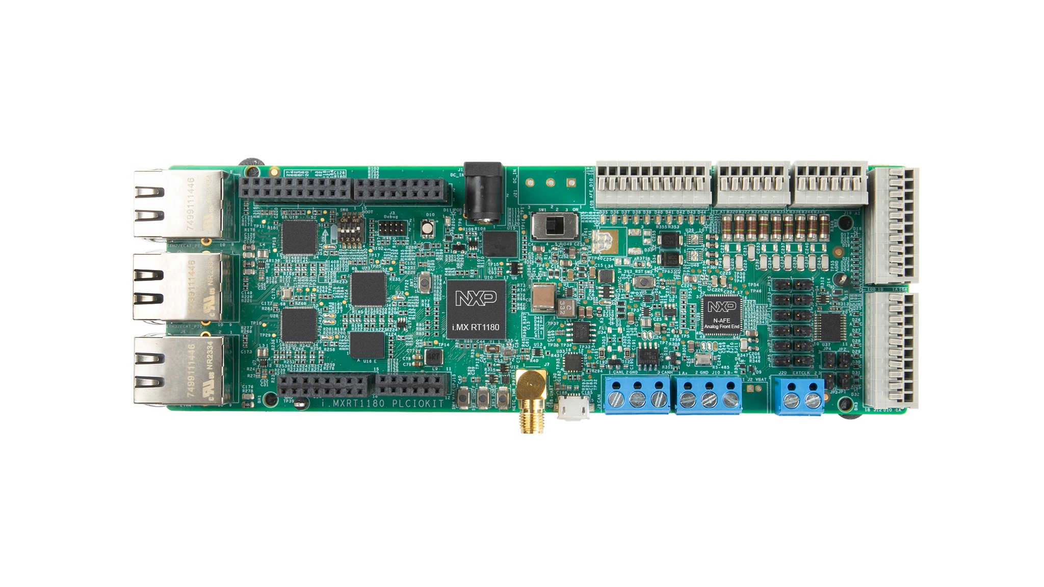
RIOP专为寻求多协议、工业实时以太网通信支持的开发人员而设计。该平台将i.MX RT1180 MCU和NAFE13388模拟前端(AFE)集成到一个经过全面测试的、模块化且可扩展的系统中。此解决方案显著加快了远程I/O以及数字和模拟I/O模块的上市进程。
该平台附带了展示其所支持工业协议的示例应用:
- 演示(开箱即用体验):通过以太网使用网络控制器(NETC)与PC上的FreeMASTER进行通信,提供直观的开箱即用体验
- 以太网控制自动化技术示例应用(ECAT示例应用):通过与PC上由TwinCAT驱动的软可编程逻辑控制器(soft-PLC)应用进行通信,演示恩智浦的 EtherCAT协议实现
4. 配置硬件
4.1 配置硬件
注:该板可通过外部电源端口使用24V或5V适配器供电,也可通过连接至UART转USB端口的Micro-USB线供电。使用Micro-USB端口时,将不使用电源开关。可以同时使用外部电源和Micro-USB线。
在运行应用前,请执行以下步骤:
-
配置
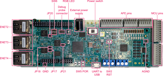
SW6开关设置启动模式(每个引脚可设置为ON [向上]或OFF [向下]),然后将位置设置为:1: OFF,2:ON,3:OFF,4:OFF - 将
JP17和JP18连接到位置2-3 (即最左侧和中间引脚,其编号顺序为3-2-1) - 将24V外部电源连接到可编程逻辑控制器输入/输出(PLCIO)板
- 给板上电
- 通过以太网线将以太网端口4 (
ENET4)连接至PC - 使用Micro-USB线连接板与PC
5. 运行应用
5.1 将FreeMASTER连接至板
将FreeMASTER工具连接到板的步骤如下:
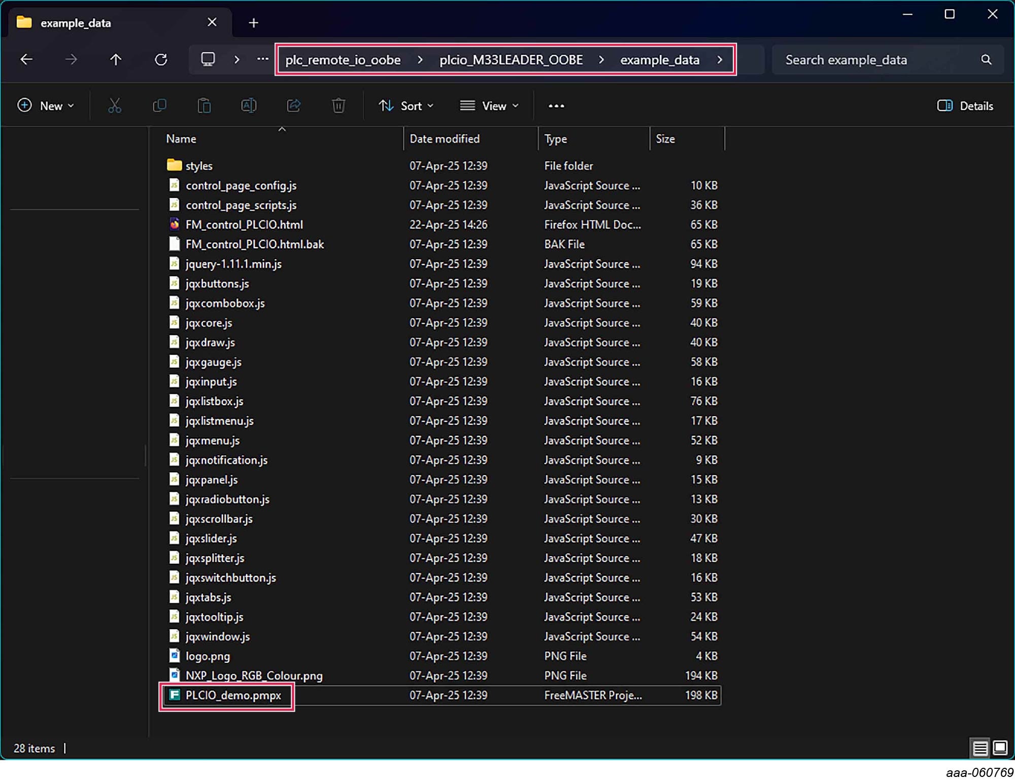
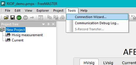
- 打开下载的RIOP软件包的文件夹,然后转到“riop_M33LEADER_DEMO/example_data”,打开“RIOP_demo.pmpx”
- FreeMASTER应用将启动
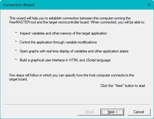
- 进入"Tools" → "Connection Wizard"(工具→连接向导)
- 点击“下一步”
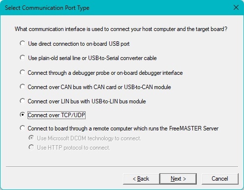
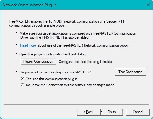
- 选择“通过TCP/UDP连接”,然后点击“下一步”
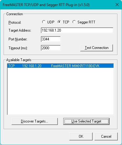
- 点击“插件配置”
- 点击“发现目标”,然后选择一个可用目标,按下“使用所选目标”,再点击“确定”
- 点击“完成”
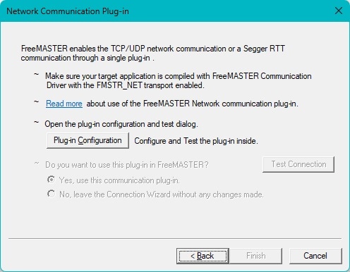
FreeMASTER现已连接到板,可以使用应用程序了。
5.2 测试连接
要测试连接,请按照以下步骤测量外部电压信号:
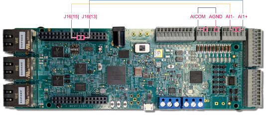
- 将蓝色导线连接到
J16[13]和AI1+(从左数第5个引脚) - 将黄色导线连接到
J16[15]和AI1-(从左数第4个引脚) - 将黑色导线连接到模拟输入公共端(
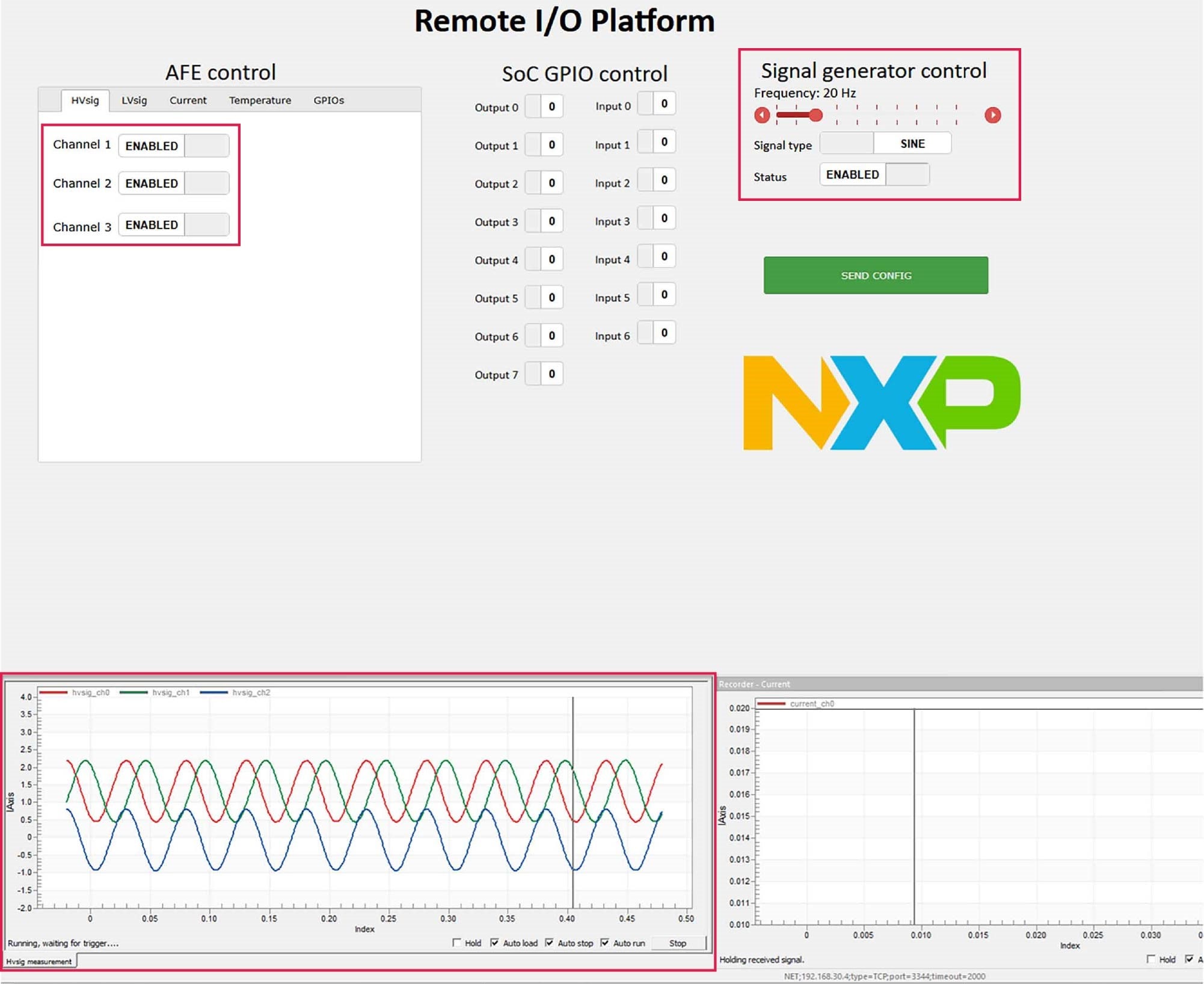
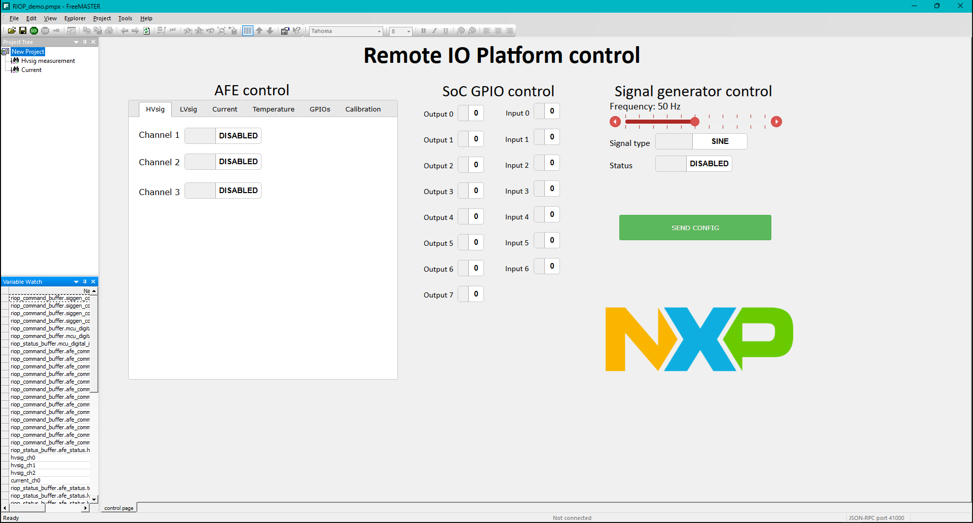
AICOM) (从左数第3个引脚)和模拟接地端(AGND) (从左数第6个引脚) - 在FreeMASTER应用中启用信号发生器
- 在“高压信号”("HVsig")选项卡中,启用一个或多个通道
- 按下“发送配置”按钮
- 在记录器“HVsig”窗口中查看信号波形
- 在项目树中双击“高压信号测量”按钮,切换到“高压信号”视图(或者,也可以右键点击“高压信号测量”按钮并选择“New window”(新建窗口)以显示它,如图13所示)。
启用“SINE”(正弦波)时,通道1和3之间存在偏移,通道2显示为其他两个波形的差值(但当启用“SAWTOOTH”(锯齿波)时,通道之间没有偏移,通道2显示为0)。