FRDM-A-S32K344通用开发板快速入门
上次修改时间:
Mar 8, 2026支持
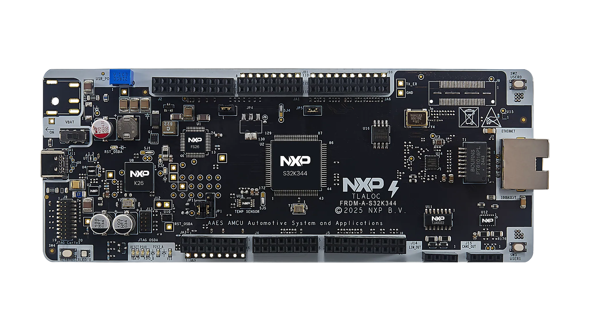
FRDM-A-S32K344开发板
1. 开箱即用

2. 获取软件
使用账号登录恩智浦官网。
2.1 安装软件
- 通过以下链接访问软件包:FRDM Automotive套件
- 点击“生成”进行下载
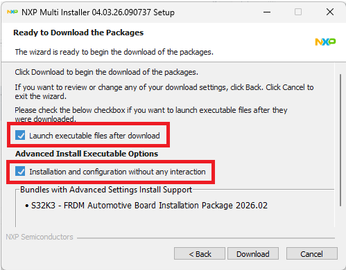
- 运行恩智浦多重安装程序
- 通过已创建的桌面快捷方式启动S32 Design Studio for S32 Platform 3.6.5
通过勾选"下载后启动可执行文件"(Launch executable after download)和"无需任何交互的安装与配置"(Installation and configuration without any interaction)选项,FRDM软件包及其所有可用组件将被一并安装。
所有软件及工具现已自动完成安装与配置。
3. 连接
3.1 连接电源
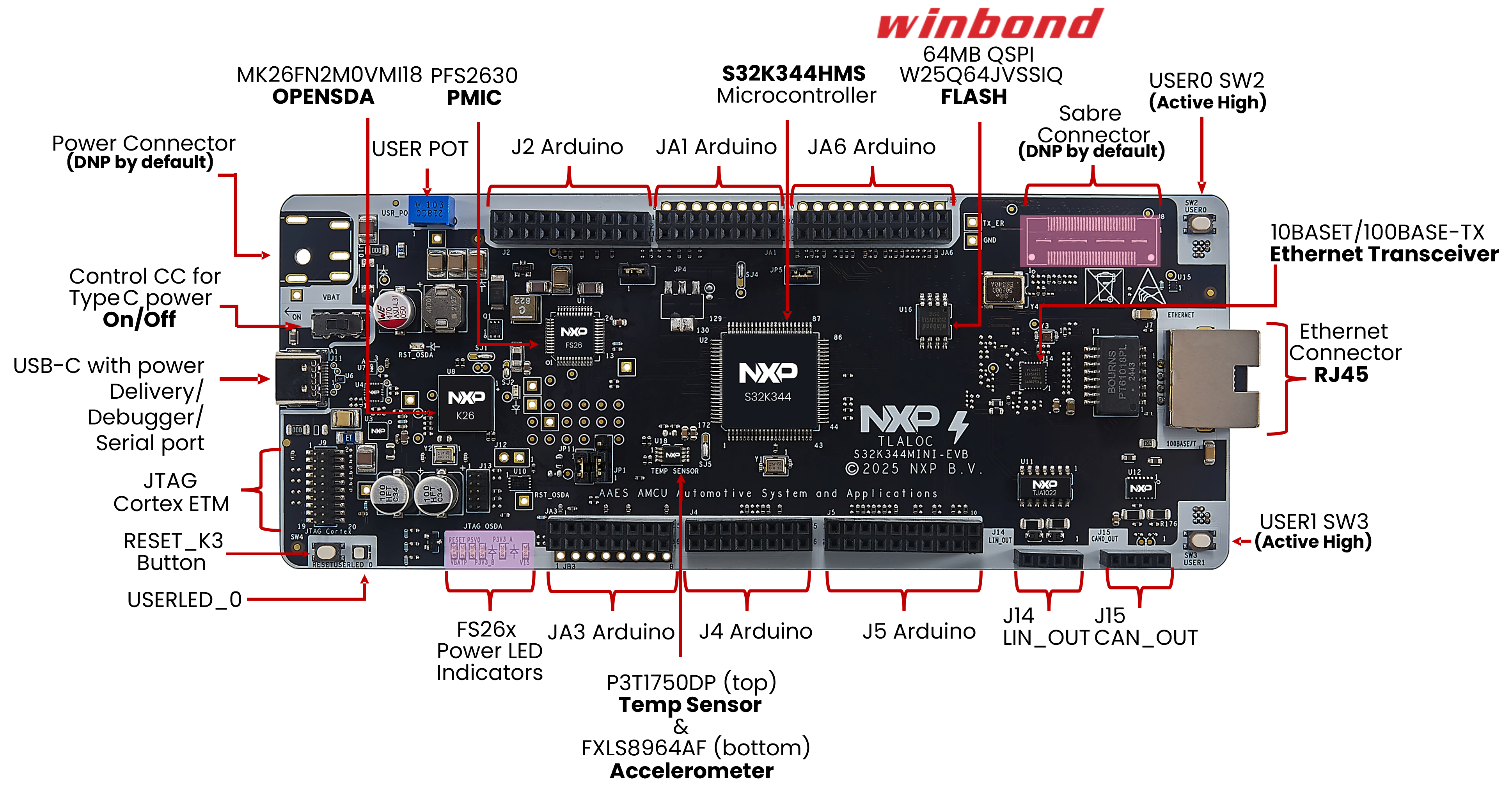
FRDM-A-S32K344是一款基于S32K344EVB-Q172的快速原型设计板。该板并非为最终量产用途设计,因此采用通过USB Power Delivery连接至FS26 SBC的主电源选项。
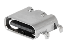
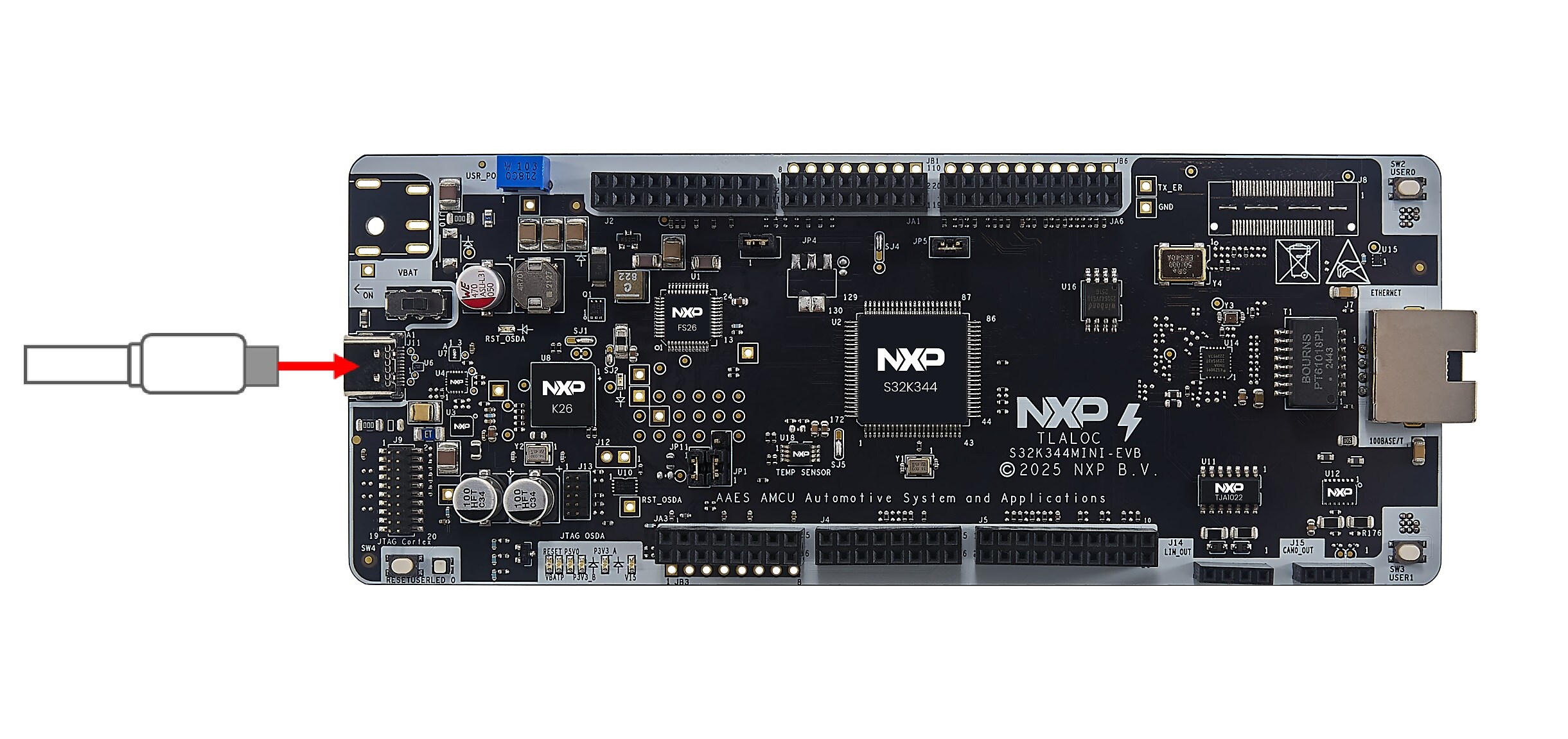
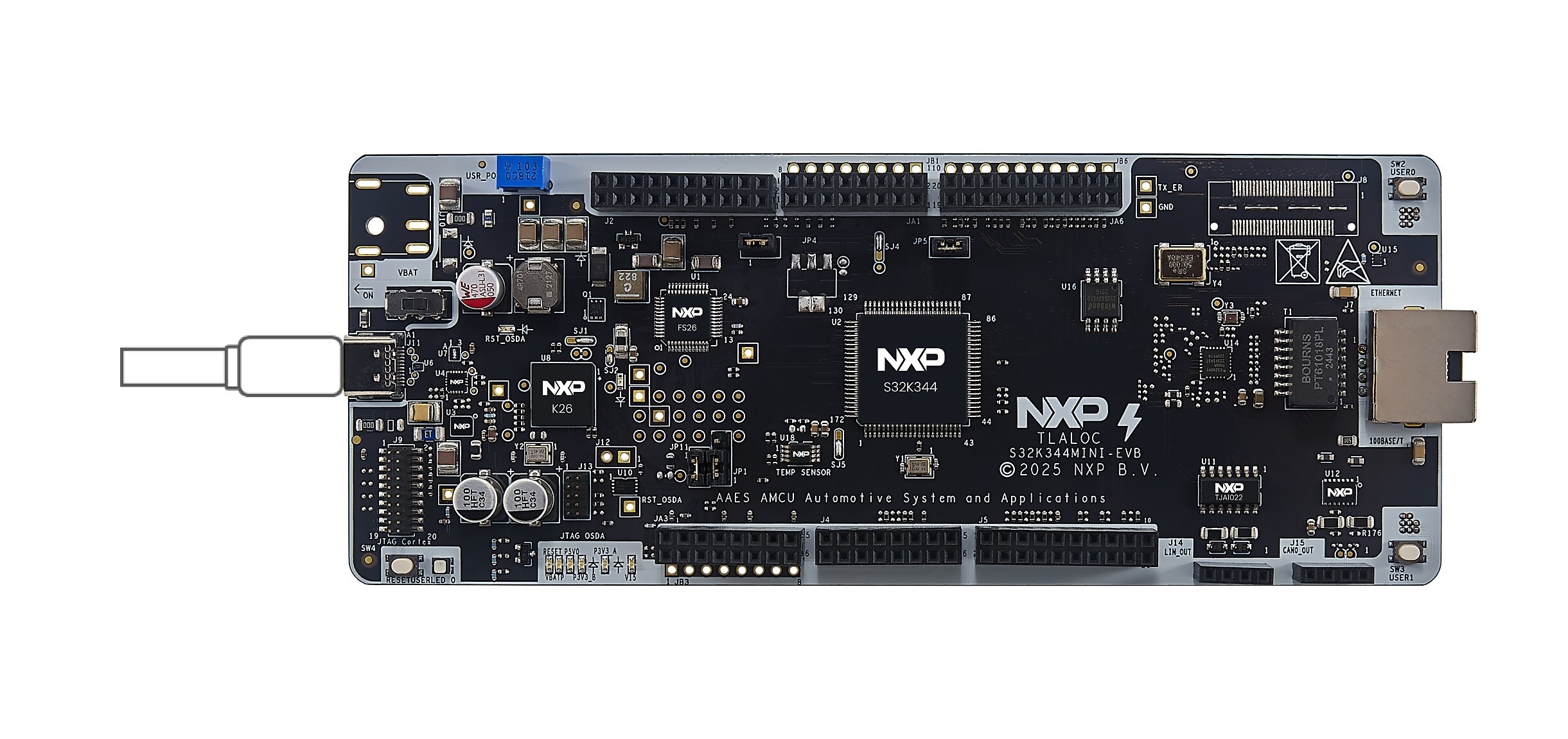
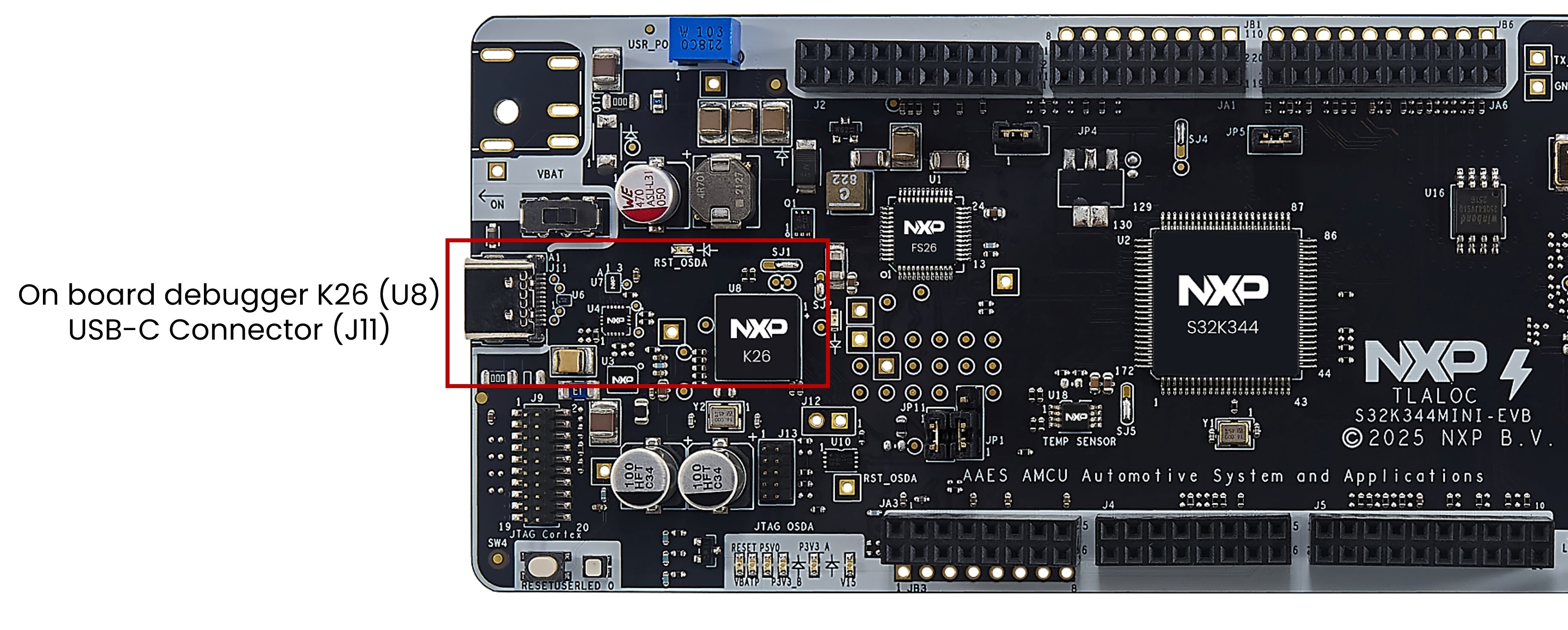
默认情况下,FRDM-A-S32K344通过J11 USB-C连接器供电。建议使用随附的USB-C线,或任何支持USB Power Delivery (PD)的线缆,以确保板的全部功能正常运行。使用不合规的线缆可能导致电流供应受限,并降低性能。
要正常为板供电,需要使用支持USB-C PD的电源,例如USB-C PD充电器或支持PD协议的笔记本电脑。虽然大多数现代笔记本电脑都支持USB PD,但使用前请确认您的设备是否具备此功能。
FRDM-A-S32K344支持高达20V的输入电压。但根据FS26 SBC的建议,最佳工作电压范围为9V、12V或15V,且电流至少为1A。要实现上述电压和电流,需要USB PD电源与PD PHY (PTN5110)之间进行正确的协商。有关如何在S32K344上实现此协商的指导,请咨询当地的恩智浦现场应用工程师(FAE),或访问恩智浦应用代码中心网站获取相关代码。
3.2 启动顺序
- 将USB-C线连接至
J11连接器,给板上电 - 要给板上电,将开关SW5的默认位置更改为2-3设置
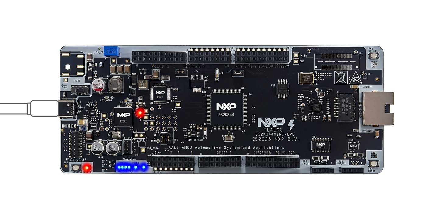
- 确认板上的所有电源指示灯均已亮起
4. 构建、运行
设计资源
支持
培训
论坛
访问恩智浦的技术社区网站,与其他工程师交流,获取如何使用FRDM-A-S32K344开发板进行产品设计的专业建议。