Getting Started with the RD9Z1-638BJBEVM
本文档内容
-
Out of the Box
-
Get Hardware
-
Configure the Hardware
-
Install Software
-
Learn More
1. Out of the Box
The NXP analog product development boards provide an easy-to-use platform for evaluating NXP products. The boards support a range of analog, mixed-signal, and power solutions. They incorporate monolithic integrated circuits and system-in-package devices that use proven high-volume technology. NXP products offer longer battery life, a smaller form factor, reduced component counts, lower cost, and improved performance in powering state-of-the-art systems.
This page will guide you through the process of setting up and using the RD9Z1-638BJBEVM board.
1.1 Kit Contents/Packing List
The RD9Z1-638BJBEVM contents include:
- Assembled and tested RD9Z1-638BJBEVM board in an anti-static bag
- 10-pin high voltage connector cable
- 7-pin high-voltage connector cable
- 5-pin high-voltage connector cable
- 4-pin low voltage connector cable
- Quick Start Guide
1.2 Additional Hardware
In addition to the kit contents, the following hardware is necessary or beneficial when working with this kit.
- USB-enabled PC Workstation with Windows 7 or above
- Low-voltage DC power supply, 5.0 V to 12 V output with current limit set initially to 1.5 A
- High-voltage DC power supply, 0 to 1000 V output
- Current load, 0 to 500 A
- CAN card and cable (optional)
- PEmicro's Multilink Universal Debug Probe
1.3 Windows PC Workstation
This reference design requires a Windows PC workstation running 32-bit and 64-bit versions of Windows 7 or above.
1.4 User Manual
Refer to UM11396, RD9Z1-638BJBEVM reference design for additional details on the featured components and board configuration.
2. Get Hardware
2.1 Board Description
The RD9Z1-638BJBEVM provides a platform for evaluating designs that implement NXP’s MM9Z1_638 Battery Monitoring System device. It connects to a power distribution unit (PDU) and enables voltage sensing, current sensing, temperature sensing and diagnostics of the contactor status.
The kit supports evaluations in conjunction with a CAN network and is ideal for prototyping High-Voltage Battery Junction Box (HV-BJB) systems.
2.2 Board Features
- Power supply input from 5 VDC to 12 VDC
- Up to seven voltage sensing channels for high-voltage measurements
- One current sensing channel to measure charge current and discharge current
- One temperature sensing channel to measure shunt resistor temperature for calibration
- Integrated insulation resistance measurement
- One channel isolated CAN communication to BMU/VCU
2.3 Board Components
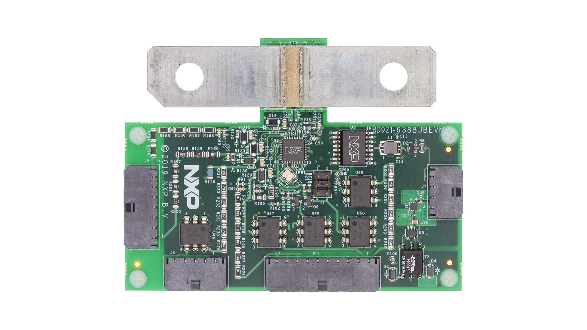
Overview of the RD9Z1-638BJBEVM: High voltage battery junction box reference design.
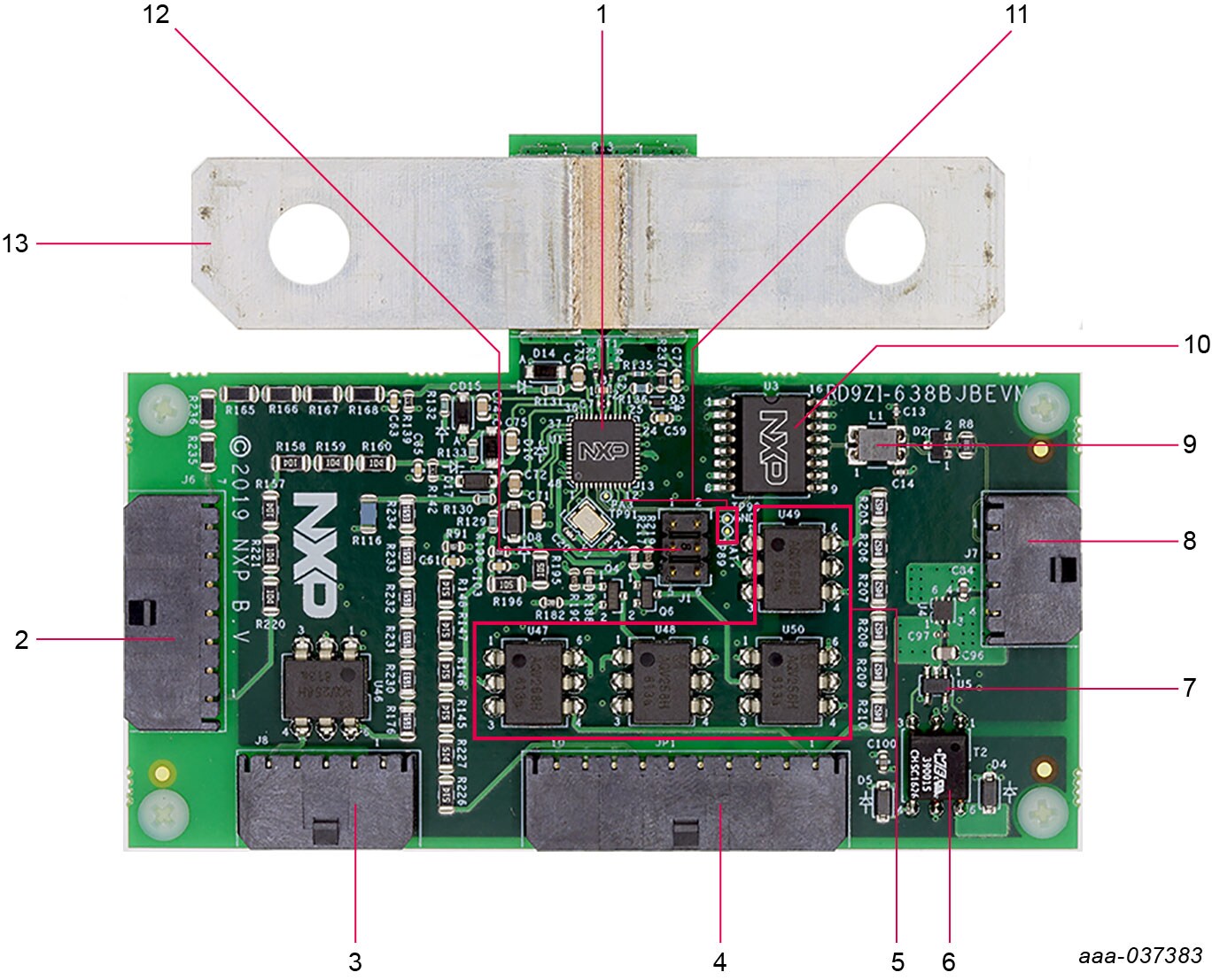
2.4 Board Description
| No. | Label | Name | Description |
|---|---|---|---|
| 1 | U1 | MM9Z1_638 | Battery Sensor with CAN and LIN |
| 2 | J6 | High-voltage connector 2 | 1x7 power plug connector |
| 3 | J8 | High-voltage connector 1 | 1x5 power plug connector |
| 4 | JP1 | High-voltage connector 3 | 1x10 power plug connector |
| 5 | U46 to U50 | Panasonic AQV258HAX | MOSFET relay |
| 6 | T2 | TI SN6501 QDBVRQ1 | Push-pull driver for small transformers |
| 7 | U5 | TI 760390015 | PMIC transformer driver |
| 8 | J7 | Low-voltage connector | 1x4 power plug connector |
| 9 | L1 | EPCOS/TDKB82789C0104N002 | Power line choke |
| 10 | U3 | NXP TJA1052IT/5Y | High-speed CAN transceiver |
| 11 | TP89, TP90, TP91 | na | Test points |
| 12 | J1 | Connector | BDM connector |
| 13 | na | na | Shunt |
Note: Refer to the bill of materials (BOM) report in Design Resources section for a complete list of part numbers.
2.5 Additional Board Support
Refer to UM11396, RD9Z1-638BJBEVM reference design for additional details on the featured components.
3. Configure the Hardware
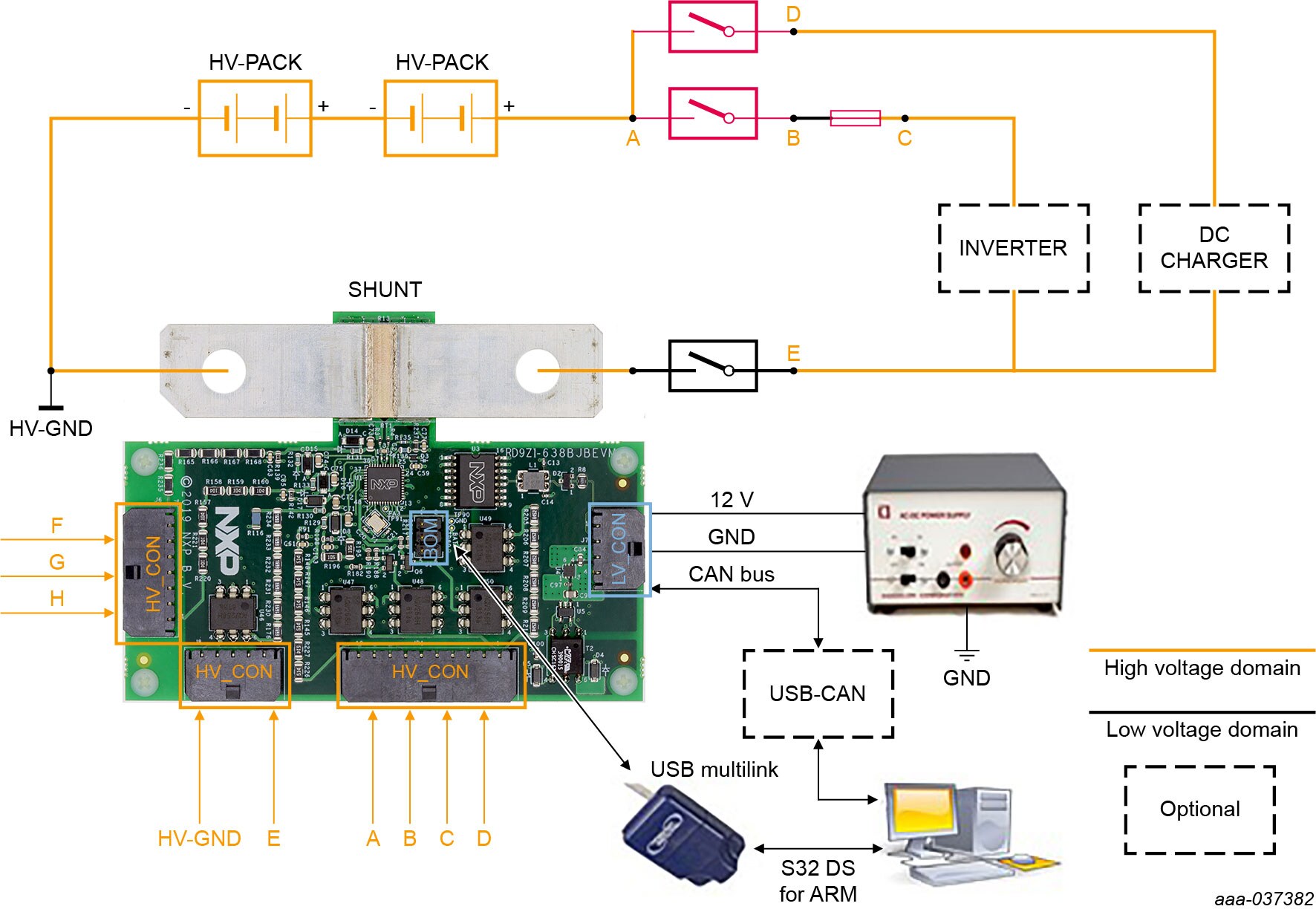
To configure the hardware, complete the following procedure:
- Connect the negative pole of the HV Battery Junction Box to one side of the evaluation board's metal shunt
- Connect the positive pole of the HV Battery Junction Box to the other side of the evaluation board's metal shunt
-
Open high-voltage connector 1
(J8)on the RD9Z1-638BJBEVM evaluation board and attach the 5-pin connector cable as follows:- Connect
J8_1to the HV ground - Connect
J8_5to the sensing position E
- Connect
-
Open high-voltage connector 2
(J6)on the RD9Z1-638BJBEVM evaluation board and attach the 7-pin connector cable as follows:- Connect
J6_1to high voltage sensing position F - Connect
J6_4to high voltage sensing position G - Connect
J6_7to high voltage sensing position H
- Connect
-
Open high-voltage connector 3
(JP1)on the RD9Z1-638BJBEVM evaluation board and attach the 10-pin connector cable as follows:- Connect
JP1_1to high voltage sensing position A - Connect
JP1_4to high voltage sensing position B - Connect
JP1_7to high voltage sensing position C - Connect
JP1_7to high voltage sensing position D
- Connect
-
Open low-voltage connector
(J7)on the RD9Z1-638BJBEVM evaluation board and attach the 4-pin connector cable as follows:- The first two terminals of the 4-pin cable are reserved for connecting to a CAN network
- Using the third terminal on the cable, connect
J7_3to the low-voltage power supply - Using fourth terminal on the cable, connect
J7_4to the low-voltage ground
- Open the probe cover and attach PEmicro's six-pin ribbon cable to the probe’s six-pin header
(Port C) - Plug the other end of the 6-pin cable into the RD9Z1-638BJBEVM evaluation board’s BDM connector
(J1) - Plug the PEmicro's USB cable into the PEmicro Universal Debug Probe’s USB port and connect the other end of the cable to a USB port on the PC workstation
3.1 Additional Board Support
Refer to UM11396, RD9Z1-638BJBEVM reference design user manual for additional details on the hardware configuration.
4. Install Software
After configuring the hardware, users have to install and configure the CodeWarrior Integrated Development Environment (IDE) software required to run the demonstration examples and to exercise the RD9Z1-638BJBEVM in an evaluation environment.
4.1 Install CodeWarrior
- Go to NXP and navigate to the CodeWarrior Development Tools site
- In the Downloads section, select and download the latest version of CodeWarrior for MCUs
- When the Choose Components screen appears, select S12Z
- When the installation wizard completes, CodeWarrior is ready to import the reference design examples
4.2 Import the Reference Design Software
The following steps describe how to download and import the reference design software and run the demo software in CodeWarrior.
- Go to the RD9Z1-638BJBEVM tool summary page and navigate to the Design Files / BOM section. Click on the link to download the design files to a local drive on the PC. Extract the design files
-
Open CodeWarrior and import the software project
- a. From the Files menu, select Import
- b. Choose General → Existing Project into Workspace, and then click Next
- c. Select root directory. Locate the project and select RD9Z1_638_BJB_CAN_demo_V2.0. Click Finish
- Select RD9Z1_638_BJB_CAN_demo_V2.0 project, and then click Project → Build Project to build the project
4.3 Additional Board Support
Refer to UM11396, RD9Z1-638BJBEVM reference design user manual for additional software details.
4.4 Ready to Use
Start embedded application development.
5. Learn More
5.2 Tool Summary Page
The tool summary page for RD9Z1-638BJBEVM reference design is at RD9Z1-638BJBEVM.
The page provides overview information, technical and functional specifications, ordering information, documentation, and software. The Getting Started provides quick-reference information applicable to using the RD9Z1-638BJBEVM reference design, including the downloadable assets.
Design Resources
Additional References
In addition to our MM9Z1_638: Battery Sensor with CAN and LIN page, you may also want to visit:
Product pages:
- MC33772B: 6-Channel Li-ion Battery Cell Controller IC
- MM912_637: Battery Sensor with LIN for 12 V Lead-acid Batteries
Tool pages:
Application pages:
Hardware pages:
Software pages: