OM-UBX100-001无线评估板快速入门
本文档内容
-
开箱即用
-
获取硬件
-
安装软件
-
配置硬件

1. 开箱即用
恩智浦的模拟产品开发板提供了一个易于使用的恩智浦产品评估平台。开发板支持各种模拟、混合信号和电源解决方案。它们采用成熟的高容量技术,整合了单片集成电路和系统级封装器件。恩智浦产品电池寿命长,设备尺寸小,组件数量少,成本低,性能高,帮助您打造先进的系统。
本页面将指导您完成设置和使用OM-UBX100-001无线评估板。
1.1 套件内含物
OM-UBX100-001无线评估板套件包含以下组件:
- 完成组装和测试的OM-UBX100-001评估板,放在防静电袋中
- 射频屏蔽罩(已装在板上)
J6和J7板接头的标准引脚接头- 带有二维码的装箱清单,该二维码可链接至OM-UBX100-001产品页面
1.2 其他硬件
除了套件内含物外,使用此板时,还需要使用以下硬件。
- FRDM-MCX MCU开发板
1.3 最低系统要求
该无线评估板需满足以下条件方可正常运行:
- 安装了Windows 10或更高操作系统的PC
- USB端口(兼容3.0、2.0或1.1)
- FRDM-MCX MCU开发板
- 如需了解详情,请查看支持的硬件
- UBX100 FreeMASTER评估GUI示例应用
- 如需了解详情,请查看工具界面(GUI)说明
- USB线,可连接PC和FRDM-MCX板,用于电力输送和数据传输
对于基本的射频操作,建议使用两套FRDM-MCX和OM-UBX100-001板组合。为评估所支持的协议及其协议栈,可能需要使用接收器或嗅探器。针对此应用场景,现有多种第三方产品可供选用。相关产品的选择及使用由用户自行决定,不在本文档涵盖范围内。
2. 获取硬件
2.1 套件概述
OM-UBX100-001是一款基于mikroBUS标准的附加板,用于评估UBX100。该板搭载了一个55.2MHz TCXO,在设备使用寿命期间提供主时钟和稳定的时钟源。OM-UBX100-001还具有宽带匹配功能,可在868MHz至928MHz的频率范围内运行。该射频匹配装置可在整个频段内提供13dBm至13.5dBm的传导输出功率。
该IC预烧写了固件,允许使用恩智浦的专有协议通过SPI命令操作设备。此外,UBX100在ROM内存中包含一个引导加载程序,可以在现场更新其固件。
2.2 板特性
表1列出了OM-UBX100-001板的主要特性。
| 板特性 | 说明 |
|---|---|
| UBX100无线单元 | UBX100是一款sub-GHz无线收发器。
|
| 电源 | 该板的供电方式通常如下:
|
| 时钟 | 该板配备一个55.2MHz TCXO,为UBX100提供参考时钟。 |
| 射频匹配 | TX和RX路径的专用匹配电路。UBX100有一个内置TRX开关,用于将两个电路连接到天线路径。
|
| 天线连接器 | 该板提供SMA天线连接器,以连接外部天线。 |
| 连接器 | 含以下功能的连接器:
|
| 其他——射频路径选择 | 通过三端电阻(R5)中的0Ω电阻选择RX引脚。 引脚 RF_IN_B为默认设置。要验证兼容性或更改,请参阅UBX100 SDK软件发布说明。 |
| 型号核准认证 | 该板已完成ETSI与FCC标准合规性测试。 |
| PCB尺寸 | 42.9mmx25.4mm——符合mikroBUS M尺寸附加板规范。 |
| 可订购部件编号 | OM-UBX100-001 |
2.3 套件推荐组件
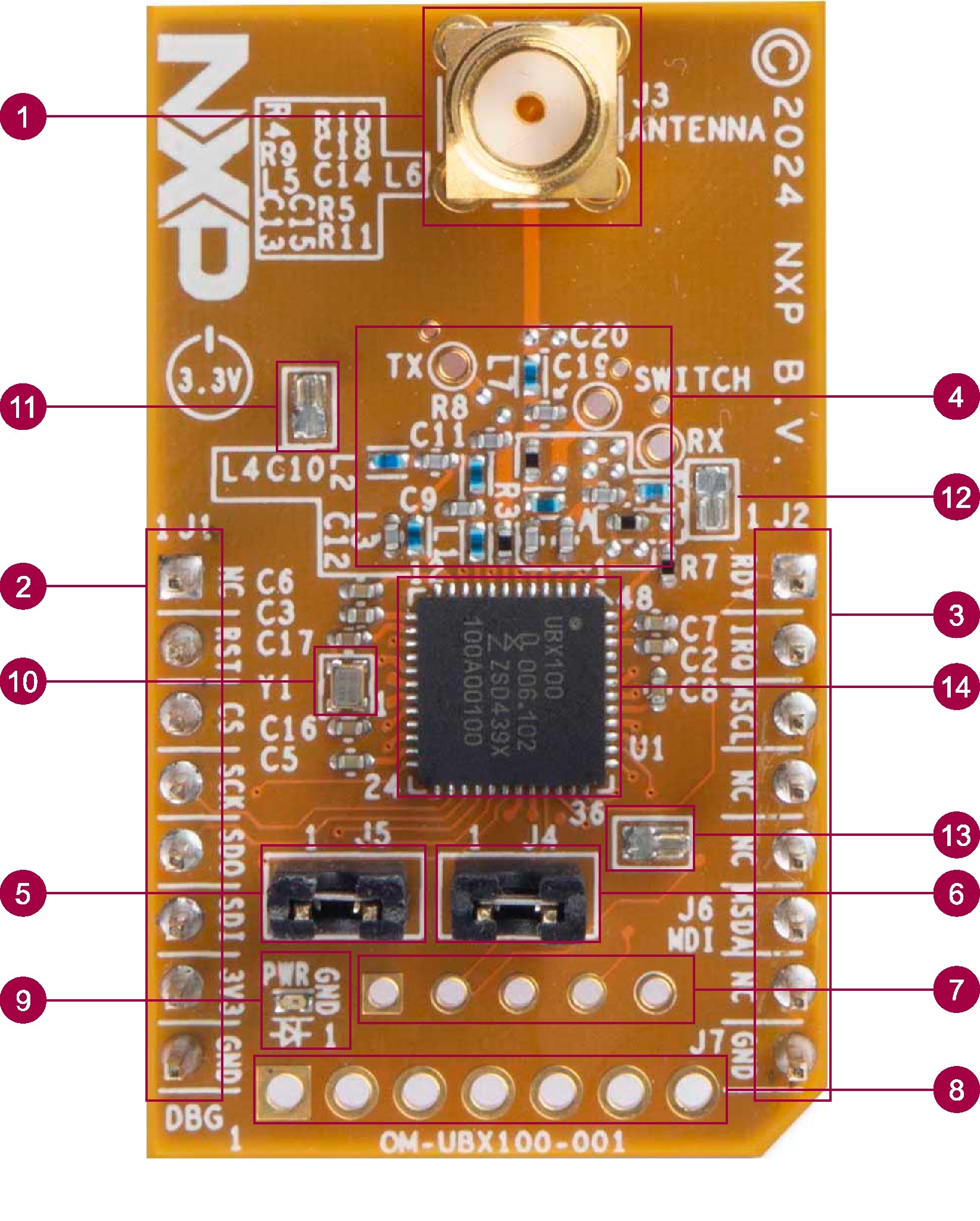
图1重点展示了OM-UBX100-001无线评估板的主要功能组件。板的物理外观可能与最终产品组装存在细微差异。
| 数量 | 名称 | 说明 |
|---|---|---|
| 1 | 天线连接器 | 用于外置天线的SMA连接器 |
| 2,3 | mikroBUS附加连接器 | 可通过mikroBUS插座连接至FRDM-MCX板 |
| 4 | 射频匹配与射频测试点 | 868MHz至928MHz频率范围内的宽带TX和RX匹配 标记为TX、SWITCH和RX的测试点 |
| 5 | 电流测量跳线 | 测量板的电流消耗(不包括电源LED) |
| 6 | MDI电源跳线 | 支持通过MDI连接器给器件供电 |
| 7 | MDI连接器 | 监测和调试接口 |
| 8 | GPIO调试连接器 | 引出UBX100专用GPIO引脚P10、P11、P20、P21、P22和P23 |
| 9 | 电源LED | 指示板是否上电 |
| 10 | TCXO | UBX100的55.2MHz时钟源 |
| 11,12,13 | 射频屏蔽罩安装夹 | 射频屏蔽罩安装点,用于提升EMC |
| 14 | 射频屏蔽罩安装夹 | 射频屏蔽罩可提升 |
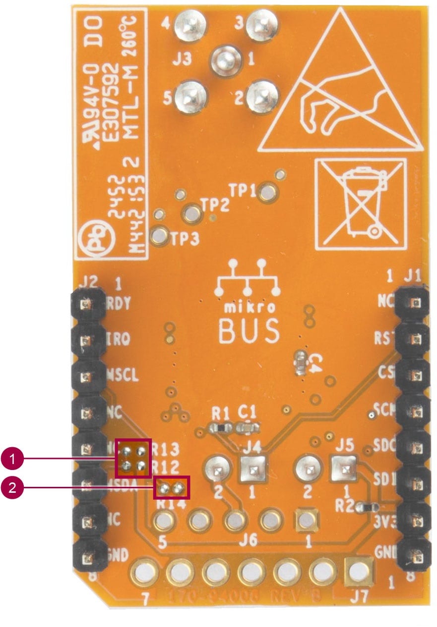
| 数量 | 名称 | 说明 |
|---|---|---|
| 1 | MDI连接器电阻 | 0Ω电阻用于将MDI信号路由至mikroBUS接头 |
| 2 | MDI MSDA上拉电阻 | 用于MSDA MDI信号的上拉电阻 |
2.4 支持的硬件
UBX100需要一个主机控制器才能运行。为此,可使用MCX系列MCU。为以下恩智浦评估板提供软件支持:
- FRDM-MCXN947
虽可兼容其他平台,但专用示例仅针对列出的板提供。恩智浦还建议您查阅UBX100和OM-UBX100-001产品页面,以获取有关支持平台和新软件包的最新信息。
3. 安装软件
3.1 安装软件
OM-UBX100-001板需与配备mikroBUS插座的FRDM-MCX开发板配套使用。如需了解硬件兼容性的详情,请查看支持的硬件。
OM-UBX100-001板预装了运行所需的固件。当发布新固件时,可通过UBX100内置的引导加载程序完成更新。相关示例应用可在UBX100和OM-UBX100-001产品页面获取。
对于FRDM-MCX板,需下载UBX100 FreeMASTER评估GUI应用并将其烧写至该板。此应用是评估FRDM-MCX和OM-UBX100-001板的主要示例。该GUI提供了基于FreeMASTER的界面,用于控制OM-UBX100-001板,以便进行简单的射频评估。运行此示例需先安装FreeMASTER Lite。访问FreeMASTER下载该软件并查看安装指南。
UBX100 FreeMASTER评估GUI示例包内含:
- 面向FRDM-MCXN947板的MCUXpresso项目
- 该项目的HEX格式二进制文件支持烧写到FRDM板上。
- GUI启动器
要烧写FRDM-MCXN947板,可编译并烧写随附的MCUXpresso项目。也可选择通过MCUXpresso工具LinkFlash将随附的HEX文件直接烧写至板。
FRDM-MCX板的软件支持(含UBX100的示例应用与固件更新)可从UBX100或OM-UBX100-001页面下载。
4. 配置硬件
4.1 配置硬件
评估OM-UBX100-001板所需的基本材料清单如下。
- 1块OM-UBX100-001板
- 1根SMA天线(50Ω阻抗,兼容868MHz至928MHz频段)
- 1块FRDM-MCX开发板
- 1根USB-A转USB-C线
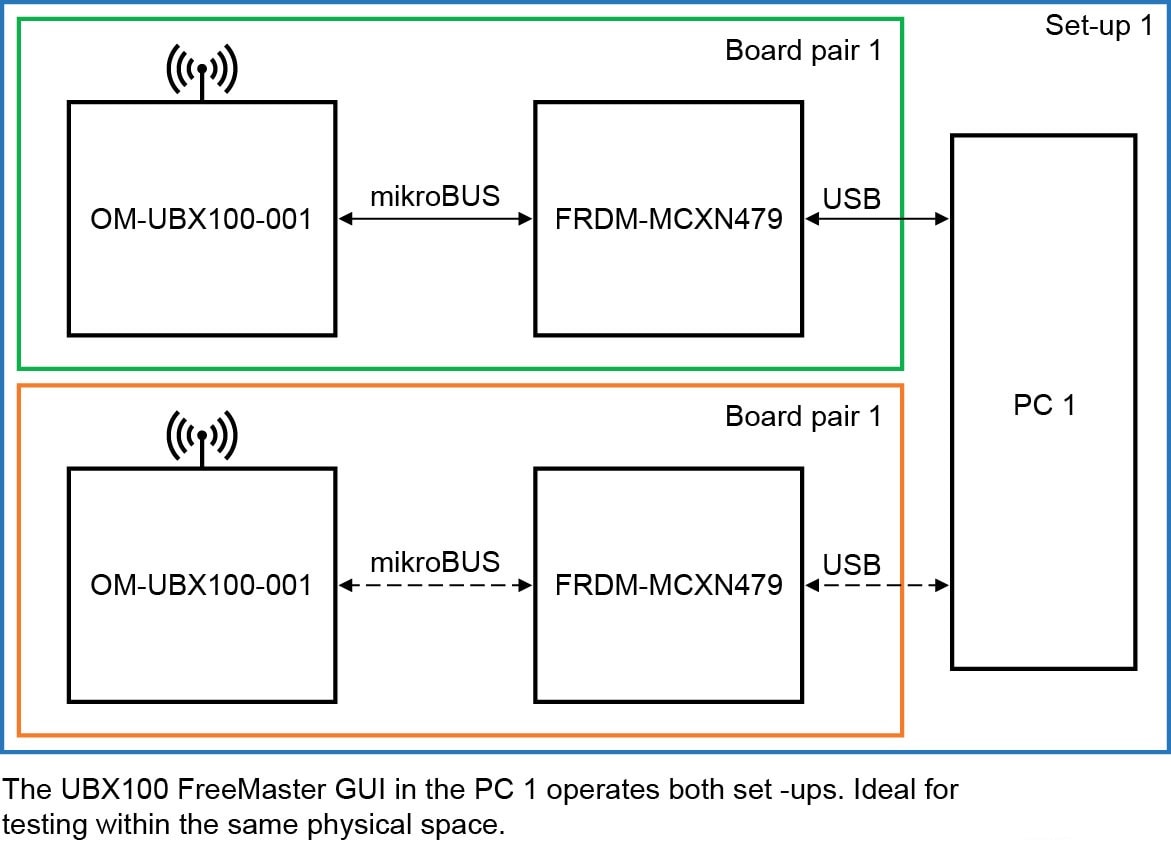
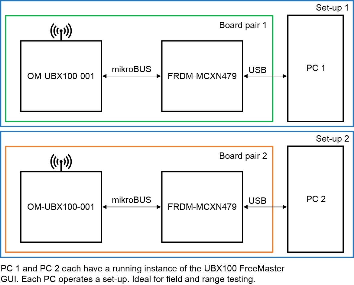
UBX100 FreeMASTER评估GUI在同一主机PC上测试两套FRDM-MCXN和OM-UBX100-001板组合。也可使用两台独立的PC分别操作不同的板组合。该配置特别适用于应用中的距离测试功能。图3和图4展示了不同设置选项的简化图。
以下步骤介绍了测试板的设置流程。FRDM-MCXN947被用作主机微控制器板的参考。
- 配置OM-UBX100-001板的电源跳线
- 安装
J5。进行电流分析时,可移除J5,然后连接DMM或能耗分析仪。 - 可选:移除
J4
- 安装
- 将天线连接至SMA连接器
- 未连接天线可能导致射频运行时因负载失配引发异常。例如,电流消耗增加
- 可选:将射频屏蔽罩安装至板的安装夹
- 默认安装屏蔽罩
- 将OM-UBX100-001板连接至FRDM-MCXN947上的mikroBUS插座
- 确保mikroBUS插座丝网印刷凹口与OM-UBX100-001的凹口对齐
- 通过USB-A转USB-C线将FRDM-MCXN947板连接至主机
- 使用FRDM板上带有MCU Link标签的USB-C连接器
- FRDM-MCXN947现已上电。该器件还通过mikroBUS插座中的3V3引脚给OM-UBX100-001板供电
- OM-UBX100-001板中的绿色LED亮起,表示板已通电
- 该设置已就绪,可与UBX100 FreeMASTER评估GUI配套工作