- 模拟工具箱
- KIT6X02AP2T1快速入门
KIT6X02AP2T1快速入门
上次修改时间:
Feb 15, 2026支持
计算机至(ETPL) Dongle
本文档内容
-
开箱即用
-
硬件介绍
-
配置硬件
1. 开箱即用
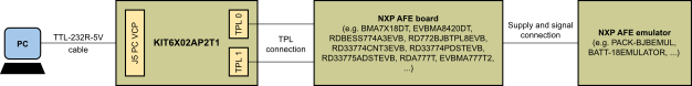
KIT6X02AP2T1用于将恩智浦PC软件(即设备评估GUI) 连接至TPL连接的恩智浦器件(即BMA7118、BMA7418、BMA8420等)。参阅该板的软件部分。
本文档旨在指导用户如何使用KIT6X02AP2T1。
1.1 套件内含物/装箱单
KIT6X02AP2T1套件内含:
- KIT6X02AP2T1——PC至电气传输协议链路(ETPL)网关板
- TTL-232R-5V——USB转RS232线(1.8m)
- ETPL线——两线双绞线TPL线缆(50cm)
2. 硬件介绍
2.1 板概述
恩智浦的模拟产品开发板提供了一个易于使用的恩智浦产品评估平台。开发板支持各种模拟、混合信号和电源解决方案。它们采用成熟的高容量技术,整合了单片集成电路及系统级封装器件。
KIT6X02AP2T1是一个硬件工具,支持用计算机上运行的软件对ETPL器件进行评估。该评估板可直接连接到PC的USB端口,并通过虚拟COM端口(VCP)进行连接。
图1为KIT6X02AP2T1的概述图。
2.2 板特性
KIT6X02AP2T1的主要特性包括:
- 通过USB连接(VCP)从PC直接控制
- VCP通信速度2MBd
- KIT6X02AP2T1由USB供电
- 两个电隔离的ETPL端口
- 支持TPL3协议版本
- 四个状态LED
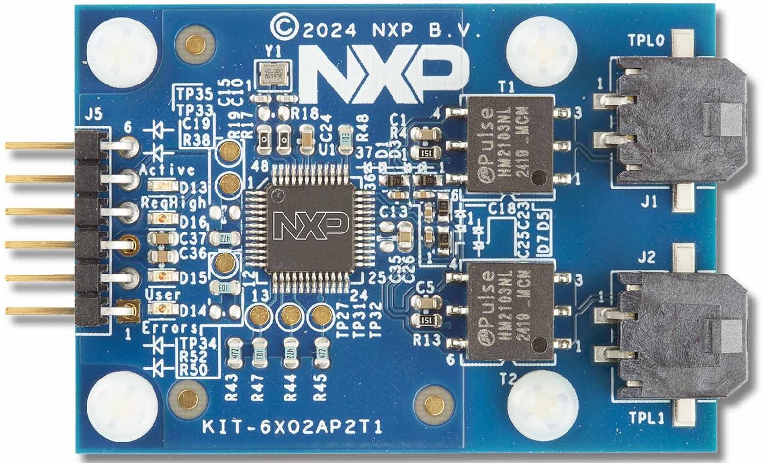
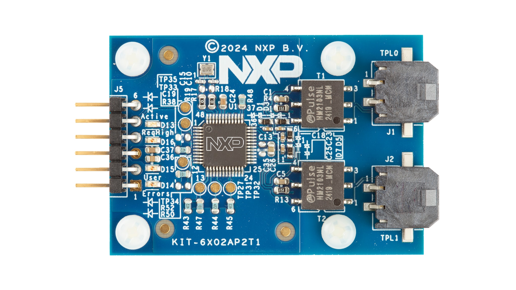
2.3 板组件
KIT6X02AP2T1使用户能够将ETPL链/器件与在PC上运行的软件连接。
该套件包含一根UART转USB转换线(TTL-232R-5V)和一根ETPL线。UART转USB转换线用于与基于UART的BMA6402网关连接,并提供5V电源。两个ETPL端口允许连接至具有恩智浦ETPL接口的恩智浦评估板或客户板。
KIT6X02AP2T1有以下LED指示灯,用于向用户指示信息。D13指示BMA6402的工作模式(活动)。D14、D15和D16 LED连接至BMA6402的GPIO,取决于BMA6402的配置。默认用途如表1所列。
| LED | 说明 | BMA6402信号 |
|---|---|---|
D13——绿色 |
活动:指示BMA6402工作状态 | STB_OUT_N |
D16——橙色 |
ReqHigh (默认用途):指示请求队列高状态 | GPIO0 |
D15——橙色 |
用户(默认用途):可选用于用户目的 | GPIO1 |
D14——红色 |
错误(默认用途):可选用于指示错误状态 | GPIO3 |
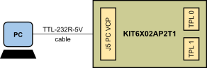
2.4 连接器
KIT6X02AP2T1有一个用于连接PC的连接器以及两个TPL端口。
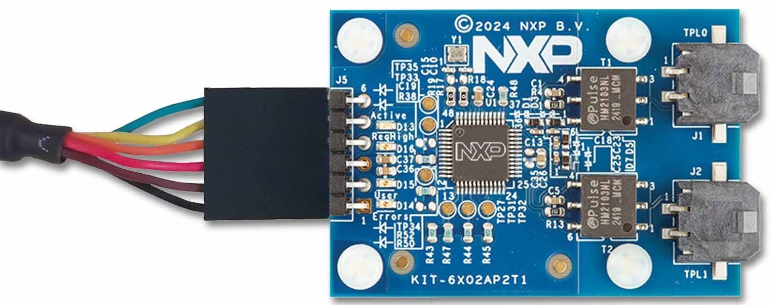
J5连接器将KIT6X02AP2T1连接至UART转USB转换线。TTL-232R-5V的引脚1 (黑色导线)必须连接至J5引脚1,如图3所示。
| 引脚数 | 连接 | 说明 |
|---|---|---|
1 |
GND | 接地 |
2 |
ReqHigh | 请求队列高输出(连接至PC UART CTS输入) |
3 |
VDD5V | 5V电源输入 |
4 |
ReqData | 请求数据输入(连接至PC UART TXD输出) |
5 |
RspData | 响应数据输出(连接至PC UART RXD输入) |
6 |
Hold | 保持输入(可选连接至PC UART RTS输出) |
J1和J2连接器连接至KIT6X02AP2T1的TPL端口0和端口1。
| 引脚数 | 连接 | 说明 |
|---|---|---|
1 |
TPL1_P |
TPL端口1 (正) |
2 |
TPL1_N |
TPL端口1 (负) |
| 引脚数 | 连接 | 说明 |
|---|---|---|
1 |
TPL0_P |
TPL端口0 (正) |
2 |
TPL0_N |
TPL端口0 (负) |