i.MX 95 19mmx19mm EVK板快速入门
1. 开箱即用
本节介绍启动i.MX 95 19mmx19mm评估套件(EVK)板的操作步骤。按照演示视频的指导,采用i.MX 95 19mmx19mm EVK开始开发应用。如需了解更多信息,请访问i.MX 95应用处理器文档。
1.1 套件内含物
i.MX 95开发套件包含:
- i.MX 95 19mmx19mm EVK板:系统级模块(SOM)和基板(BB)
- 线缆:两根USB数据线,USB 3.0 A/M转Type-C线,1米
- 电源:AC/DC适配器,12V/13.33A,160W
- 软件:Linux板级支持包(BSP)镜像烧写到eMMC中
- 快速入门指南
- i.MX 95 19mmx19mm EVK板散热片安装指南
- 7mmx5.28mmx12mm,带散热胶带,铝材质产品编号:HS070712070723
- 9mmx7.3mmx12mm,带散热胶带,铝材质产品编号:HS090912070723
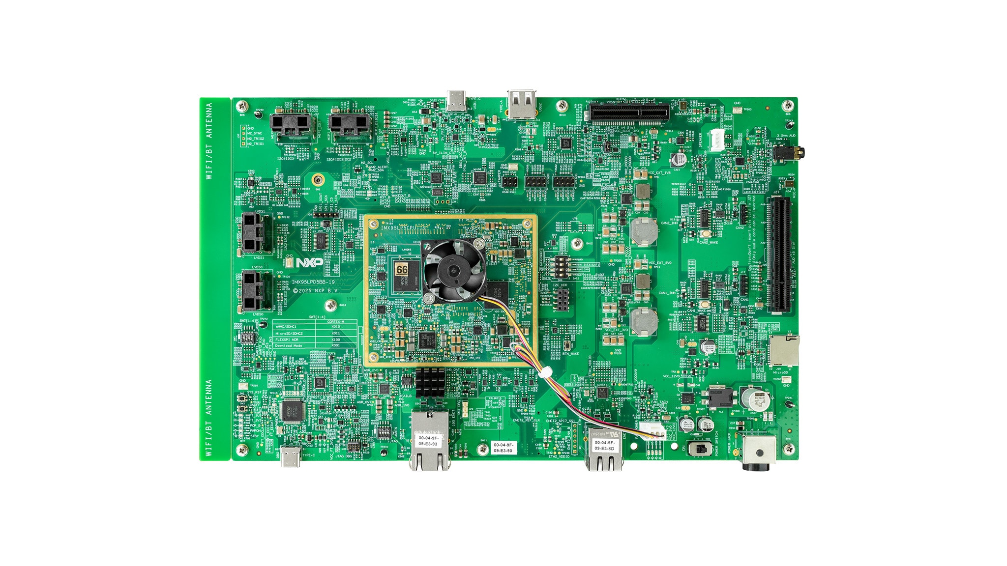
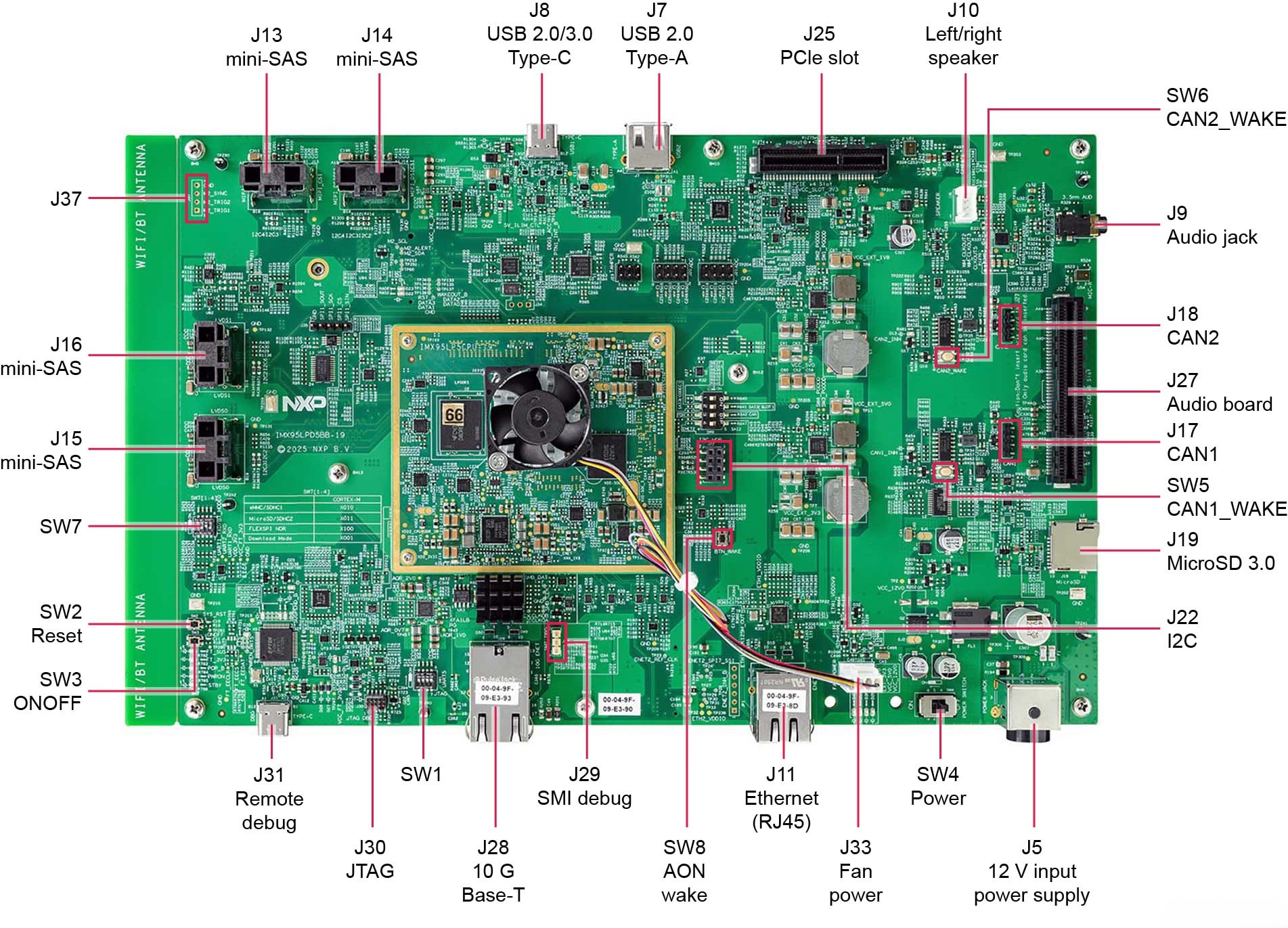
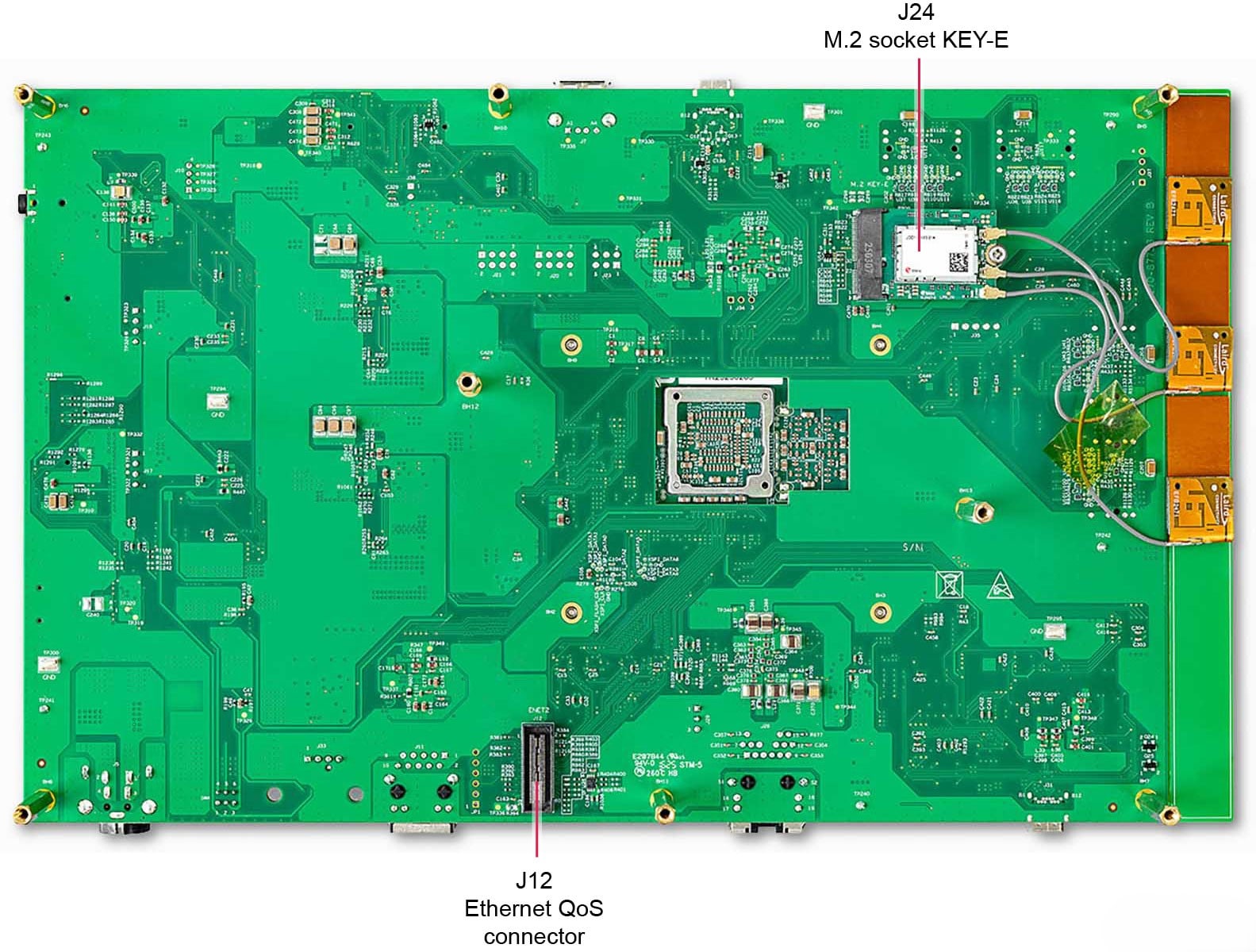
1.2 熟悉板
1.3 从eMMC启动
i.MX 95 19mmx19mm EVK配备一个预构建的恩智浦Linux二进制演示镜像,烧写在eMMC上。无需修改内部的二进制文件,从eMMC启动将提供具有某些功能的默认系统,用于在Linux上构建其他应用。
后续章节将详细介绍恩智浦的Embedded Linux。
1.4 连接USB调试线缆
- 将随附的USB Type-C线连接至调试UART端口
J31,然后将线的另一端连接到主机 - 主机上将显示四个UART连接
- 第三个端口用于A55内核,第四个端口用于M33内核系统调试
如果您不熟悉终端应用,请先查看以下任一教程,再继续步骤1.5:Minicom教程、Tera Term教程、PuTTY教程。
要在Linux下进行调试,请确保已安装FT4232 Linux驱动程序 。
1.5 连接HDMI显示器
要体验镜像二进制文件所提供的用户界面,请使用J14连接器连接一块IMX-MIPI-HDMI板(需单独采购),然后通过HDMI线将板的另一端连接至HDMI显示器。
1.6 启动开关设置
有关启动开关设置的指导,请参阅下表。如需了解更多关于i.MX 95 19mmx19mm EVK的信息,请参考快速入门指南或i.MX 95 19mmx19mm EVK板用户指南。
| 启动模式 | SW7-1 | SW7-2 | SW7-3 | SW7-4 |
|---|---|---|---|---|
| 串行下载器 | x | 0 | 0 | 1 |
| USDHC1 8位eMMC 5.1 | x | 0 | 1 | 0 |
| USDHC2 4位SD3.0 | x | 0 | 1 | 1 |
| FlexSPI串行NOR | x | 1 | 0 | 0 |
1.7 接通电源
- 将电源线插入电源连接器(
J5) - 板默认设置为从eMMC启动,并将开始从eMMC执行可启动镜像。随后,U-Boot应自动开始执行
- 信息在Arm Cortex-A55的串行控制台中打印
- 此时,您会看到显示器的左上角出现企鹅,然后在左上角看到Linux终端图标,在右上角看到定时器。这标志着已成功启动并正常运行
2. 获取软件
本部分仅适用于将Linux操作系统加载到板的情况。
2.1 概述
在i.MX板上启动Linux操作系统内核之前,必须先将Linux内核加载到启动设备(SD卡、eMMC等),并正确设置启动开关。
为不同的板和启动设备下载Linux BSP镜像有多种方法。
但本入门指南仅概述了将Linux BSP镜像传输到SD卡的几种方法。如需传输至板载eMMC,只需将所有命令中的"sd"替换为"emmc"即可。经验丰富的Linux开发人员也可根据需要探究其他选项。
2.2 下载恩智浦Linux BSP预构建镜像
i.MX Linux BSP包含一系列二进制文件、源代码和支持文件,可用来启动特定i.MX开发平台上的Embedded Linux镜像。
当前Linux二进制演示文件版本请参见i.MX Linux下载页面。i.MX软件和开发工具的Linux部分中的i.MX Linux文档包提供其他文档。
预构建的恩智浦Linux二进制演示镜像提供典型系统和基本的功能集,用于使用和评估该处理器。这样用户无需修改系统,就可以评估硬件接口、测试SoC功能并运行用户空间应用。
当需要更多灵活性时,SD卡可逐一与单个组件(引导加载程序、内核、dtb文件和rootfs文件)一起加载,或者,可加载*wic.zst镜像,并且特定组件可以覆盖单个部件。
2.3 使用Universal Update Utility (UUU)烧写恩智浦Linux BSP镜像
除了“开箱即用”章节的连接外,使用USB线将USB1 (J8)连接到主机。
拔下电源适配器。参考第1.6节“启动开关设置”,配置板在串行下载协议(SDP)模式启动。
根据主机使用的操作系统,将Linux BSP镜像传输到SD卡的方式可能会有所不同。从下面的选项中进行选择,获取详细指导:
Linux®主机
将UUU安装到Linux Distro
如需下载以下最新的stable文件,请访问UUU GitHub页面 。如需有关UUU的进一步帮助,请参阅本详细教程 。
uuulibusb1(通过apt-get或任何其它资源包管理器)
将恩智浦Linux BSP镜像烧写到板上
- 打开终端应用并将目录更改为
uuu及i.MX 95 19mmx19mm EVK最新Linux版本所在位置 - 向
uuu文件添加执行权限并执行,uuu等待USB设备连接 - 给板上电,
uuu开始将镜像复制到板 - 完成后,给板断电
- 参考第1.6节“启动开关设置”,配置板从SD卡启动
- 给板上电启动
$ chmod a+x uuu
$ sudo ./uuu -b sd_all to imx-image-full-imx95evk.wic.zstWindows®主机
在Windows主机上安装UUU
如需下载以下最新的stable文件,请访问UUU GitHub页面 。如需有关UUU的进一步帮助,请参阅本详细教程 。
uuu.exe- 串行USB驱动程序(取决于板和Windows安装——查看Windows设备管理器)
将恩智浦Linux BSP镜像烧写到板上
- 打开命令提示应用,转到
uuu.exe文件及i.MX 95 19mmx19mm EVK最新Linux版本所在位置 - Turn on the board and then
uuuwill start to copy the images to the board - When it finishes, turn off the board
- Consult the Section 1.6 Boot Switch Setup to configure the board to boot from SD card
- Power on the board to boot
.\uuu.exe -b sd_all to imx-image-full-imx95evk.wic.zst3. M7应用支持
i.MX 95除多个A55内核外,还配备一个M7内核。默认镜像启用M7内核。第一个UART端口用于M7内核。
3.1 部署M7应用
Update the M7 firmware by integrating custom M7 binary into the bootloader so that the M7 core automatically starts at power‑up.
To generate a new bootloader (flash.bin) that includes M7 binary, follow the MCUXpresso SDK guide: “Run a demo application — MCUXpresso SDK Documentation .”
This guide also explains how to flash the updated bootloader to microSD or eMMC storage.
3.2 运行M7应用
Once the new bootloader has been written to the selected boot device, power on the board using the appropriate boot mode switch configuration.
The M7 application log output will appear on the first UART port.
Minicom Tutorial (Under Linux)
Serial Communication Console Setup
i.MX 95 19 mm x 19 mm EVK uses FTDI FT4232 chip for the serial ports. The FTDI chip should be supported out-of-the box for the Linux. Just connect the board to a Linux host and it should be available. FTDI chip appear as /dev/ttyUSB* when they are connected.
On the command prompt of the Linux host machine, run the following command to determine the port number:
$ ls /dev/ttyUSB*
/dev/ttyUSB0  /dev/ttyUSB1  /dev/ttyUSB2  /dev/ttyUSB3
应有4个端口。假设为ttyUSB0-3。
第一个端口用于Arm® Cortex®-M7。第三个端口用于A55。第四个端口用于在M33上运行的系统管理器。
Minicom
使用以下命令安装和运行串行通信程序(以minicom为例):
- 使用Ubuntu包管理器安装Minicom
- 启动Minicom,使用先前确定的端口号通过控制台窗口进行
- 选择“串行端口设置”并输入
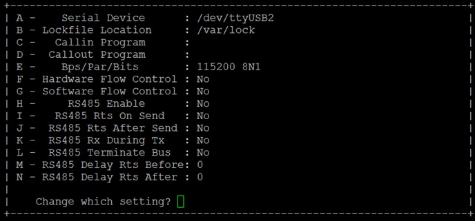
- 配置Minicom ,如下图所示
- 完成所有设置后,按回车键返回上述配置窗口,然后进入"Exit"(退出)选项卡并按回车键
- Minicom将开始显示来自板串行端口的消息
$ sudo apt-get install minicom$ sudo minicom /dev/ttyUSB2 -s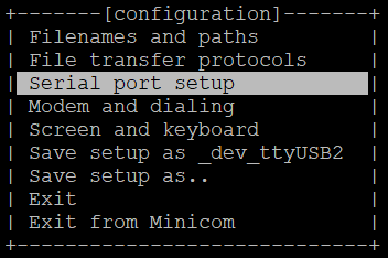
Tera Term Tutorial (Under Windows)
Serial Communication Console Setup
i.MX 95上的FTDI FT4332 USB串行芯片将枚举4个串行端口。假设端口为COM11、COM12、COM13、COM14。第一个端口(COM11)用于Arm® Cortex®-M7内核的串行控制台通信。第三个端口(COM13)用于Arm® Cortex®-A55。第四个端口(COM14)用于在Arm® Cortex®-M33上运行的系统管理器
请注意,如果连接到互联网,驱动程序将通过Windows Update自动安装。驱动程序也可通过以下链接获取:FTDI芯片 。
Tera Term
Tera Term是一款开源终端仿真应用。此程序显示从恩智浦开发平台的虚拟串行端口发送的信息。
- 下载Tera Term。下载完成后,运行安装程序,然后返回到该页面继续操作
- 启动TeraTerm
- 选择串行选项
- 假设已连接了板,列表中会自动填充4个连续的COM端口
- 配置串行端口设置(使用之前确定的COM端口号),波特率为115200,数据位为8,无奇偶校验位,停止位为1。要进行此操作,进入Setup→Serial Port(设置→串行端口)并更改设置
PuTTY Tutorial
Serial Communication Console Setup
PuTTY是一款广受欢迎的终端仿真应用。此程序显示从恩智浦开发平台的虚拟串行端口发送的信息。
- 下载PuTTY
- 下载完成后,运行安装程序,然后返回到该页面继续操作
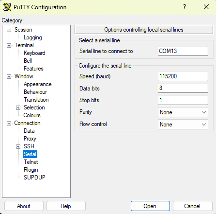
- 启动PuTTY,可双击下载的可执行文件或从“开始”菜单启动,具体取决于所选的下载类型
- 配置在启动的窗口中进行
- 选择“串行”选项,并按下图所示进行配置
- 点击“Open” (打开),打开串行连接。假设板已连接,并已输入正确的COM端口,此终端窗口会打开