MCXW72-LOC快速入门
1. 连接
现在开始试用您的板!您可以选择观看短片中的操作顺序或遵循下列详细操作步骤。
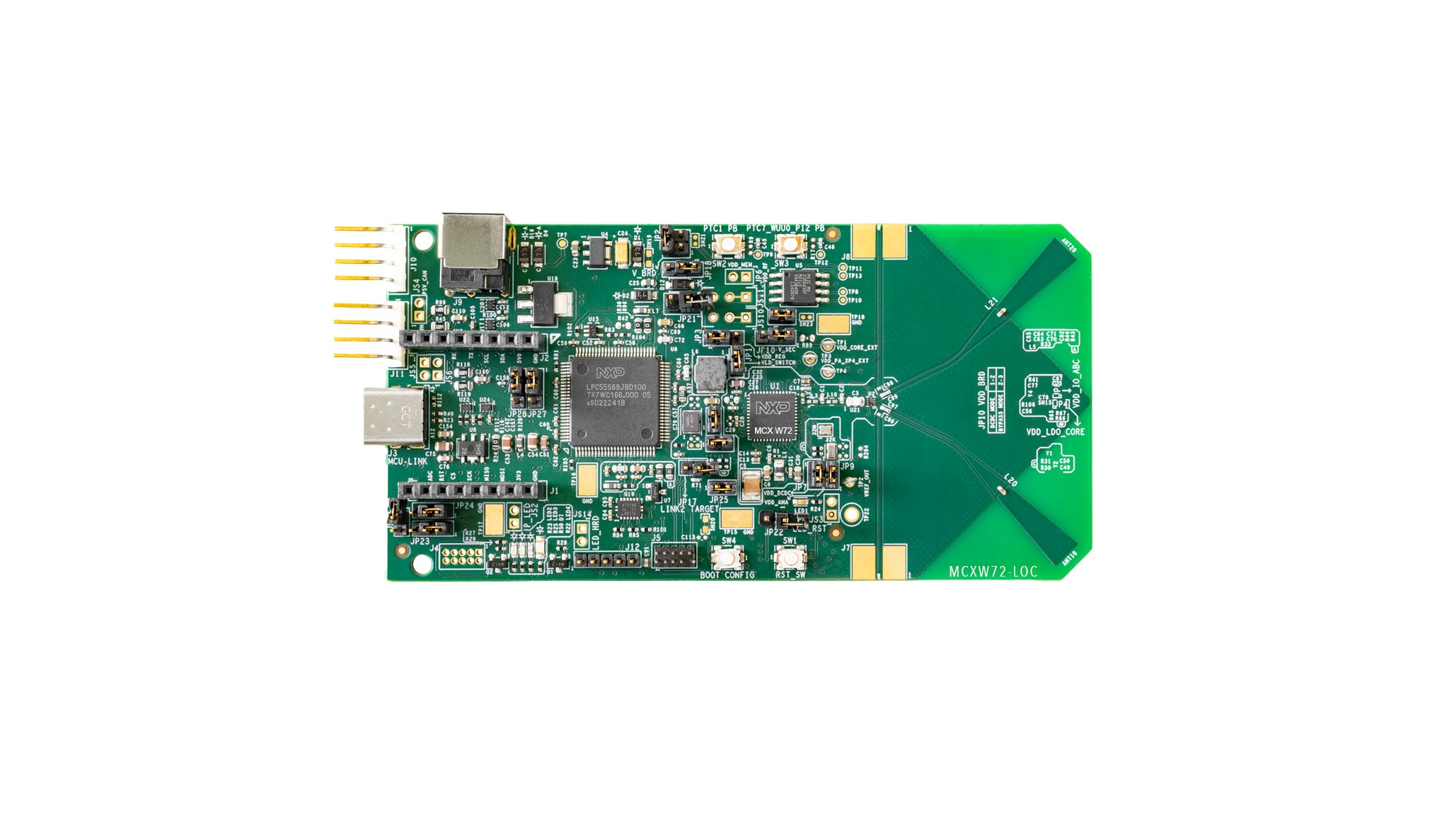
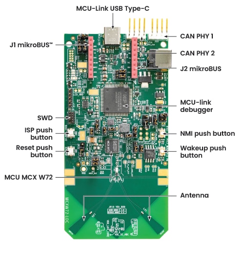
1.1 熟悉板
MCXW72-LOC板已预烧写了无线定位演示。这是一个健全性检查,用来检验设备是否能按照预期正常工作。
2. 获取软件
2.1 安装工具链
恩智浦提供名为MCUXpresso for VS Code的工具链。请下载MCUXpresso for VS Code v25.09或更高版本。
了解如何为主机安装VS Code,参考以下教程。
2.2 采用MCUXpresso SDK,快速开始设计
恩智浦扩展添加了一些工具,可以帮助将软件存储库添加到Visual Studio Code工作区。软件存储库可以从以下三个来源提供:
- 远程git URL
- 恩智浦MCUXpresso归档文件
- 现有git文件夹
本节将使用远程Git存储库选项导入MCUXpresso SDK。要以这种方式导入存储库,请执行以下步骤:
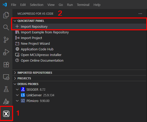
- 点击“MCUXpresso扩展”图标
- 点击“快速启动面板”选项卡,然后点击“导入存储库”按钮。按下该按钮后,将出现一个新的导入窗口
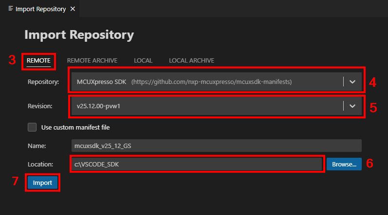
- 选择“远程”选项,导入随附的SDK文件
- 点击箭头按钮浏览“存储库”选项,并搜索“MCUXpresso SDK”选项
- 点击箭头按钮浏览“版本”选项,并搜索版本“v25.09.00”或更高版本
- 点击“浏览”,选择Location (位置)文件夹,并选择一个通用目标文件夹用于存储SDK
- 为新SDK输入名称
- 点击“导入”按钮,等待安装
2.3 MCUXpresso配置工具
MCUXpresso配置工具是一套集成的配置工具,可指导用户创建新的MCUXpresso SDK项目,还提供引脚和时钟工具,以生成支持定制板的初始化C代码。它完全集成到MCUXpresso IDE中,如果使用其他IDE,则可以将其作为单独的工具。
点击下面的“Get MCUXpresso Config Tools”(获取MCUXpresso配置工具),获取配置工具安装程序。

2.4 编程和配置工具
MCUXpresso安全配置(SEC)工具是一款基于GUI的应用,用于简化在恩智浦MCU上生成和配置可启动的可执行文件。建议所有用户首先使用MCUXpresso安全配置(SEC)工具进行试运行和大规模生产。它支持在量产阶段对恩智浦微控制器进行安全编程和设备配置。
下载该工具后,可在“帮助”选项卡下找到用户指南。按照“处理器特定工作流程”一章中针对您的板的说明进行操作。

3. 构建并运行
3.1 更新NBU固件
在运行任何无线演示之前,需要确保已将NBU固件更新至要使用的SDK版本。
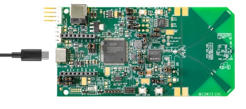
- 使用USB type-C线将MCXW72-LOC板连接至PC
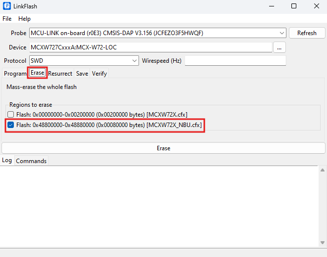
- 打开在第2.1节中安装的LinkFlash工具。该工具随LinkServer组件一同提供,其默认安装路径为“C:\nxp\LinkServer_XX.XX.XX\LinkFlash.exe”
- 在“Probe”字段中确认您的板已被工具识别。若未识别,请点击“刷新”
- 转到“擦除”选项卡,然后通过点击复选框选择NBU内存区域
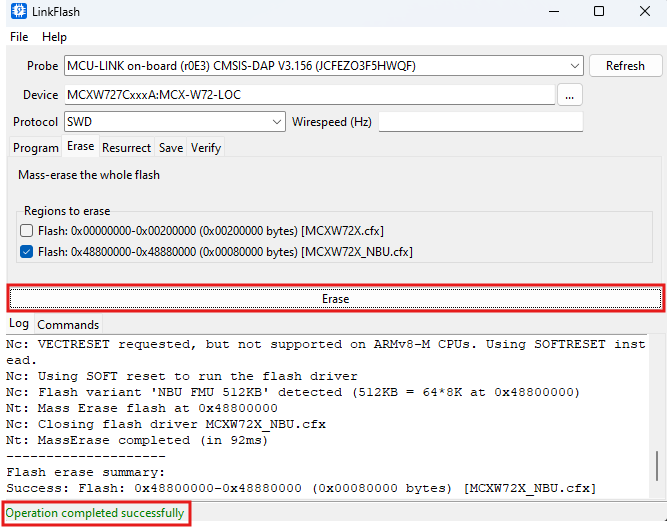
- 点击“擦除”按钮。通过窗口底部的消息验证操作是否成功
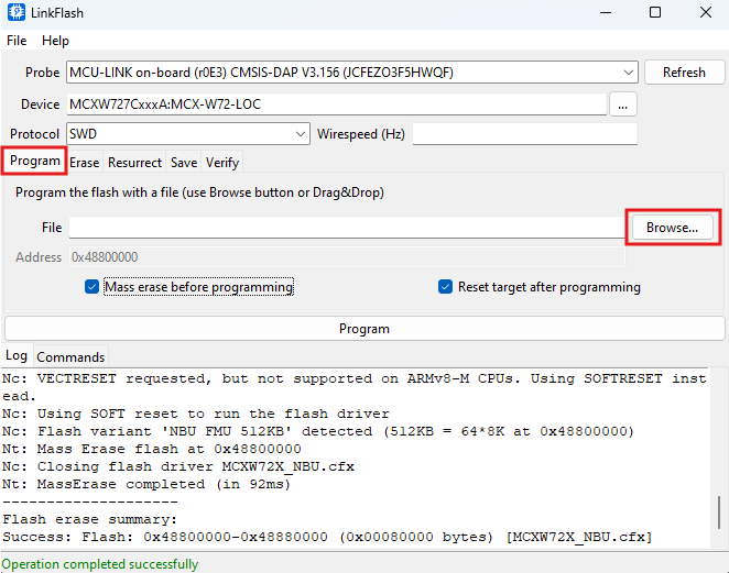
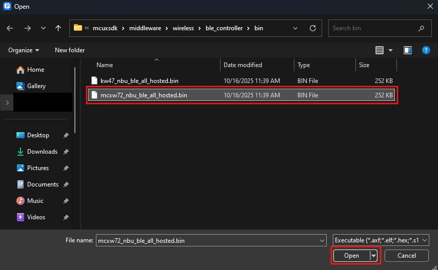
- 返回“程序”选项卡,然后点击“浏览”按钮查找NBU固件二进制文件
- 访问第2.2节中安装SDK的目录,按照路径找到NBU文件:“{your_SDK_path}\mcuxsdk\middleware\wireless\ble_controller\bin\mcxw72_nbu_ble_all_hosted.bin”。点击“打开”
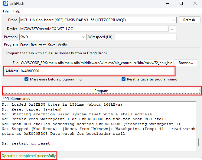
- 在“地址”字段,输入“0x48800000”。点击“程序”。验证操作是否正确完成
3.2 使用MCUXpresso for VS Code构建和烧写应用
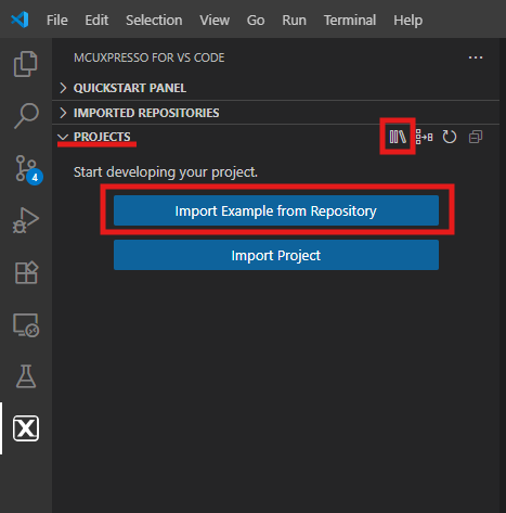
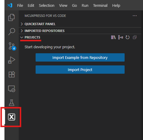
- 在左侧栏中找到活动栏,然后点击它将其打开。打开后,转到“资源管理器”并打开“项目”选项卡
- 然后点击“从存储库导入示例”
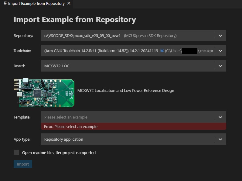
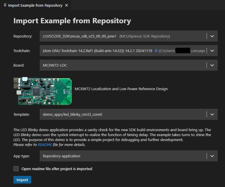
 编辑器界面上将打开以下选项卡
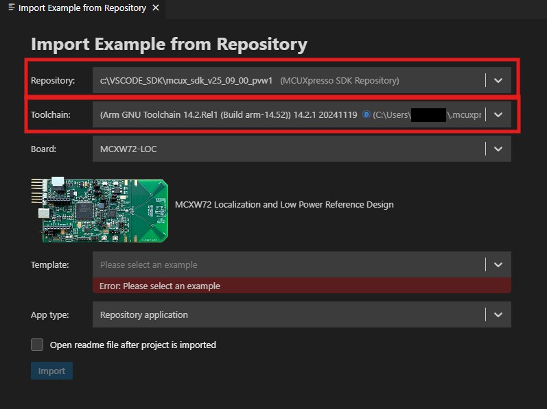
 - 点击“存储库”选项卡上的箭头按钮,选择先前下载的SDK以及与之版本匹配的工具链
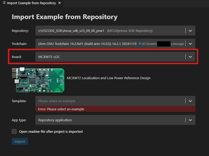
- 从“Boards”(“板”)下拉菜单中选择KW47-LOC板
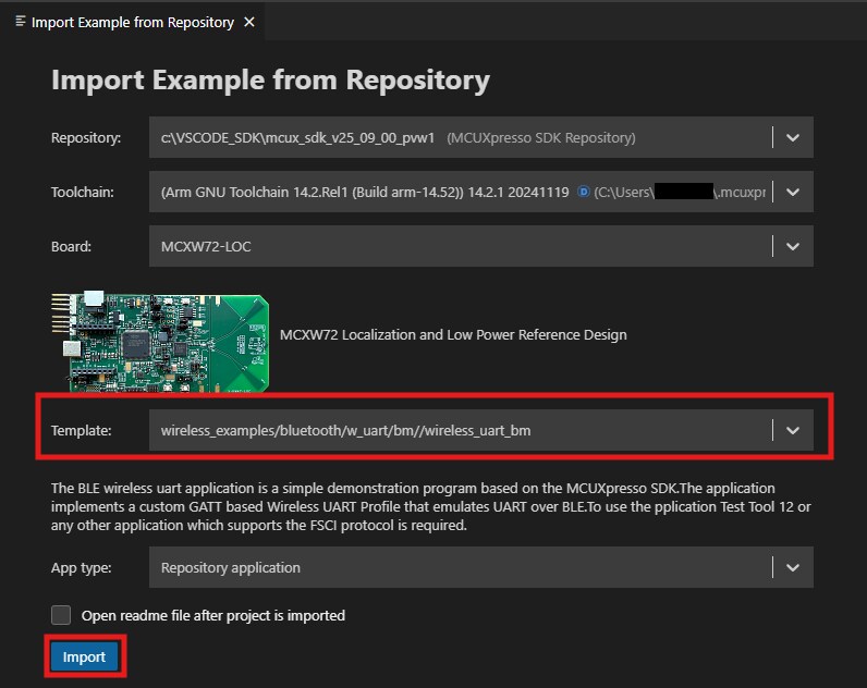
- 使用箭头按钮展开“模板”选项卡,然后选择“wireless_examples/bluetooth/bm/wireless_uart_bm”作为项目的模板。接着点击“导入”按钮
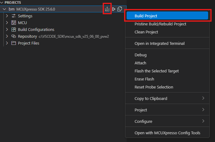
- 选择要构建的项目,点击随附快捷方式中的“build icon(构建图标)”,或者右键单击并选择"Build"(“构建”)选项
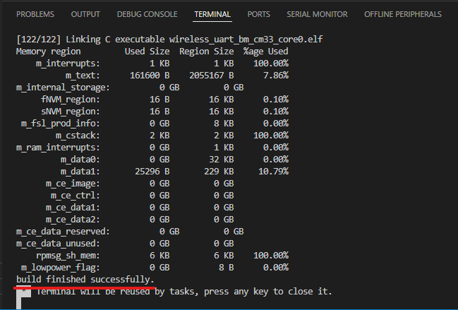
- 项目应该能够在控制台中构建完成,不会出现错误或警告
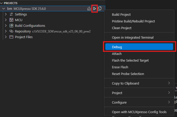
- 使用与
J3'MCU-LINK'端口连接的Micro USB将板连接到计算机 - 点击“debug(调试)”图标,或右键单击并选择"Build"(“构建”)选项,将应用下载到板上
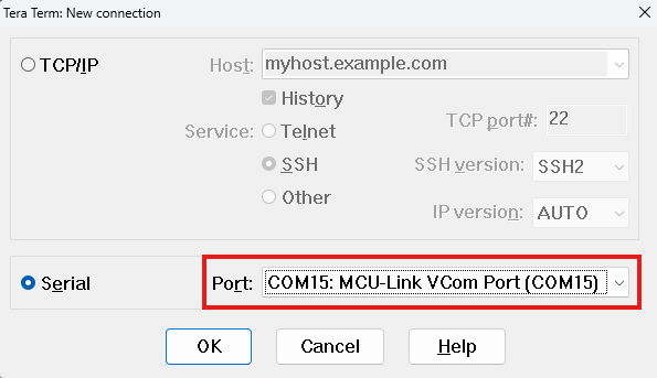
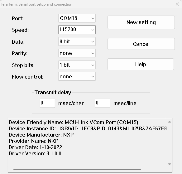
- 打开一个串行终端,以便查看应用的输出。在“MCULink-VCOM”窗口中,选择与板上的MCULINK调试器对应的端口。对终端进行设置:波特率或速率为115200,8个数据位,无奇偶校验位,1个停止位,然后连接至该端口
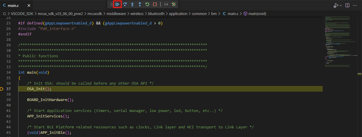
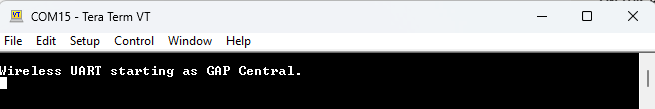
- 点击“run(运行)”图标,运行应用。 在终端上查看输出结果
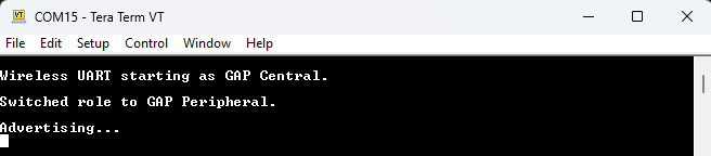
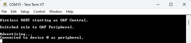
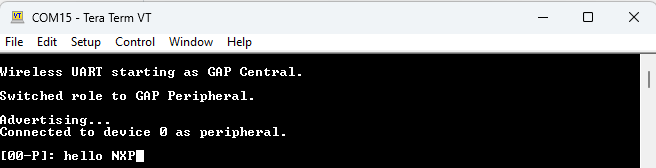
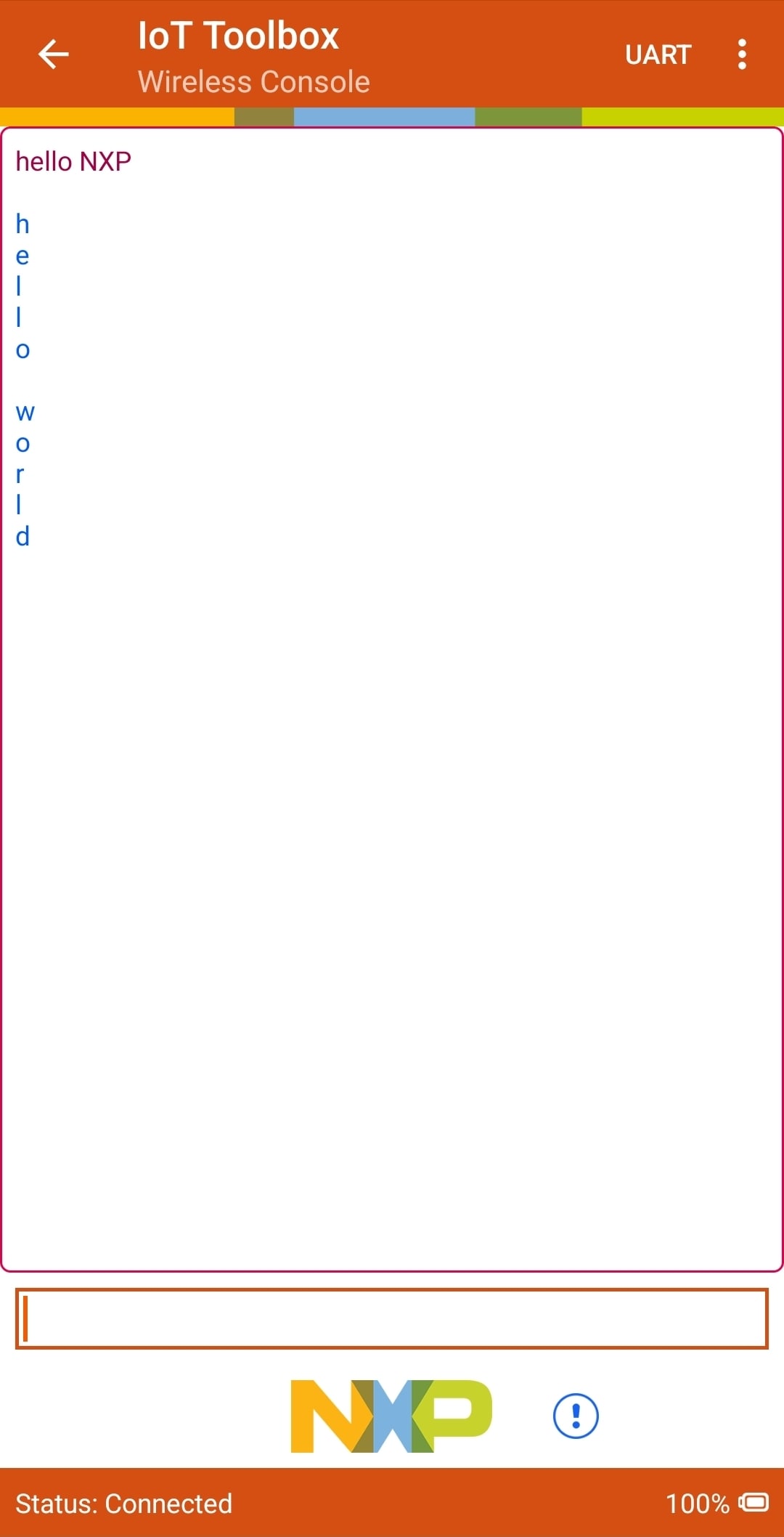
- 按下
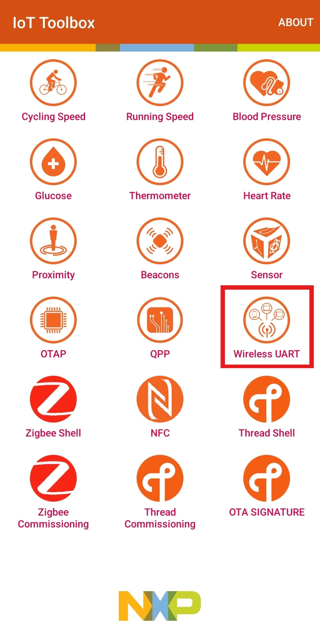
SW3按钮将BLE角色切换为“外设”。然后按SW2启动BLE广播。应该看到终端上打印的消息 - 使用IoT Toolbox应用连接该板。首先在主菜单中选择“无线UART”
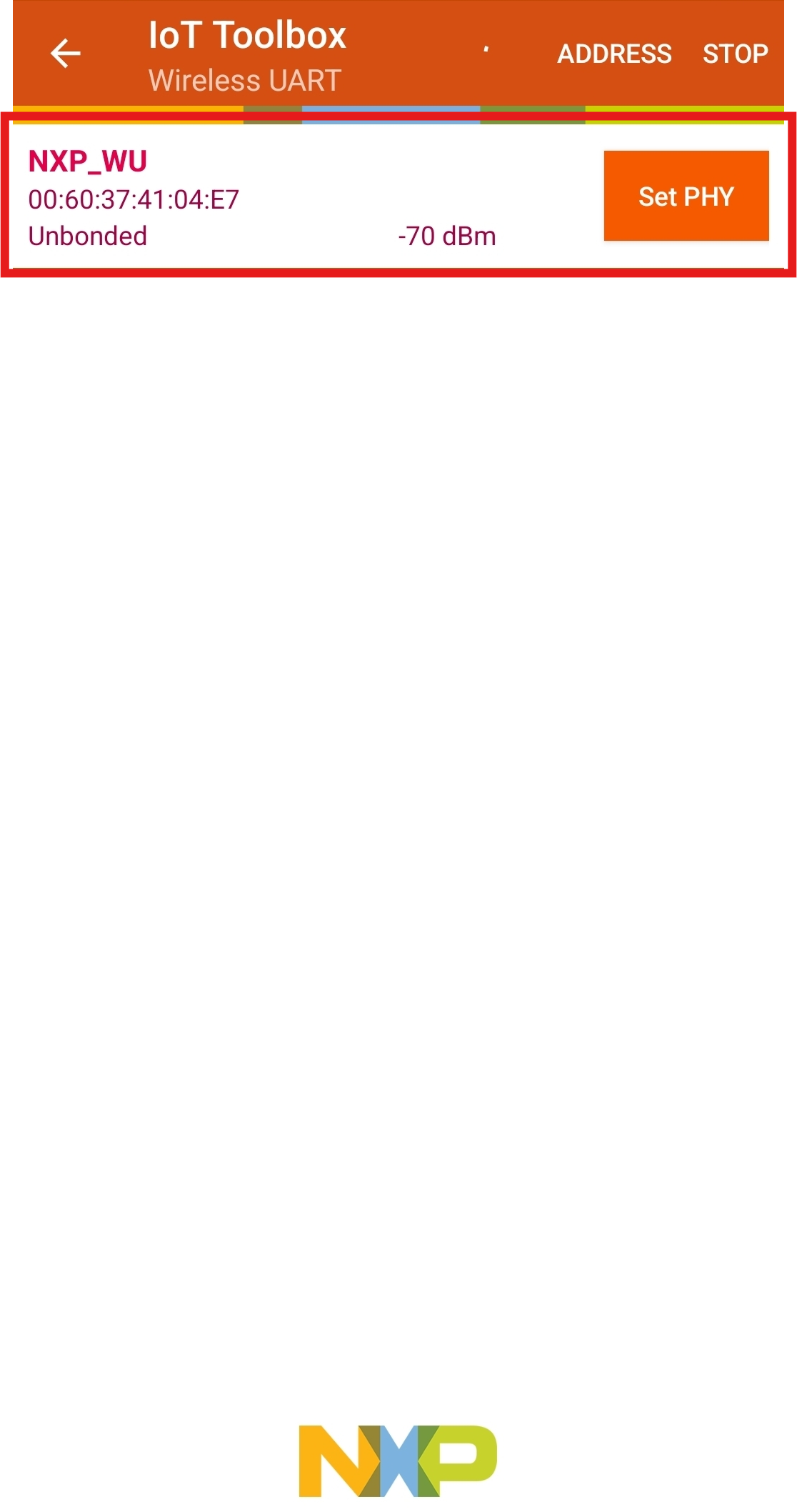
- 选择要连接的板。终端上应显示连接消息
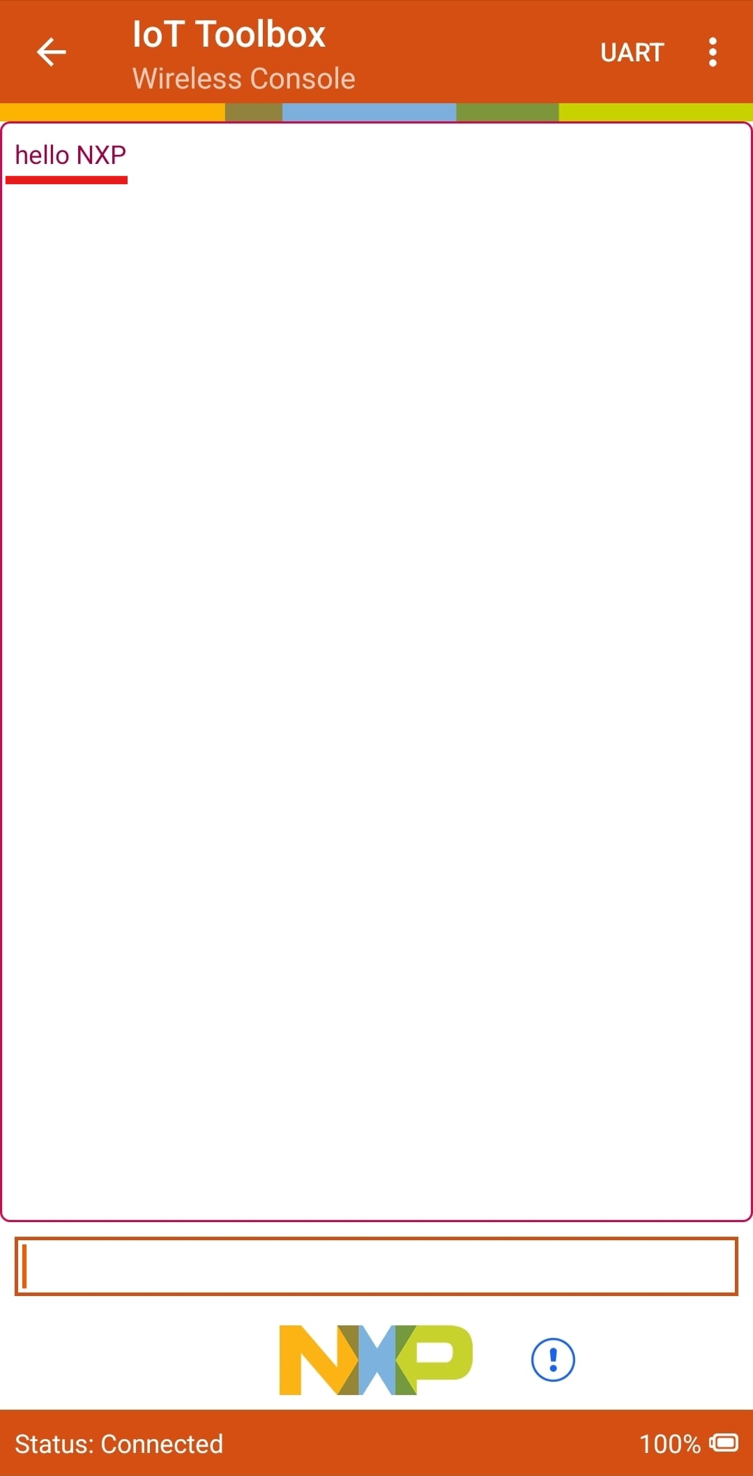
- 在该应用上输入任意一条消息,该消息将显示在终端上
- 在终端中输入一条消息,该消息将显示在应用上
4. 创建
4.1 从MCUXpresso IDE克隆示例项目
遵循以下步骤完成通用输出的操作。该示例设置了一个每秒切换一次的LED。
- 按照前一节所述,导入led_blinky SDK示例
- 在“项目”选项卡中点击“led_blinky_cm33_core0”项目,并按照上一节所述构建、编译和运行演示
- 应看到蓝色LED每秒闪烁一次
- 终止调试会话
4.2 使用MCUXpresso配置工具
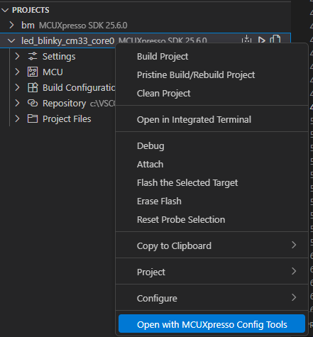
- 右键点击项目,然后选择“使用MCUXpresso配置工具打开”,即可打开引脚工具
- 选择“打开现有配置”选项。转到安装SDK的路径,然后转到“mcuxsdk\examples\_boards\kw47loc\demo_apps\led_blinky\”,选择led_blinky.mex文件,并点击“完成”
- 引脚工具现在应该显示Blinky LED项目的引脚配置
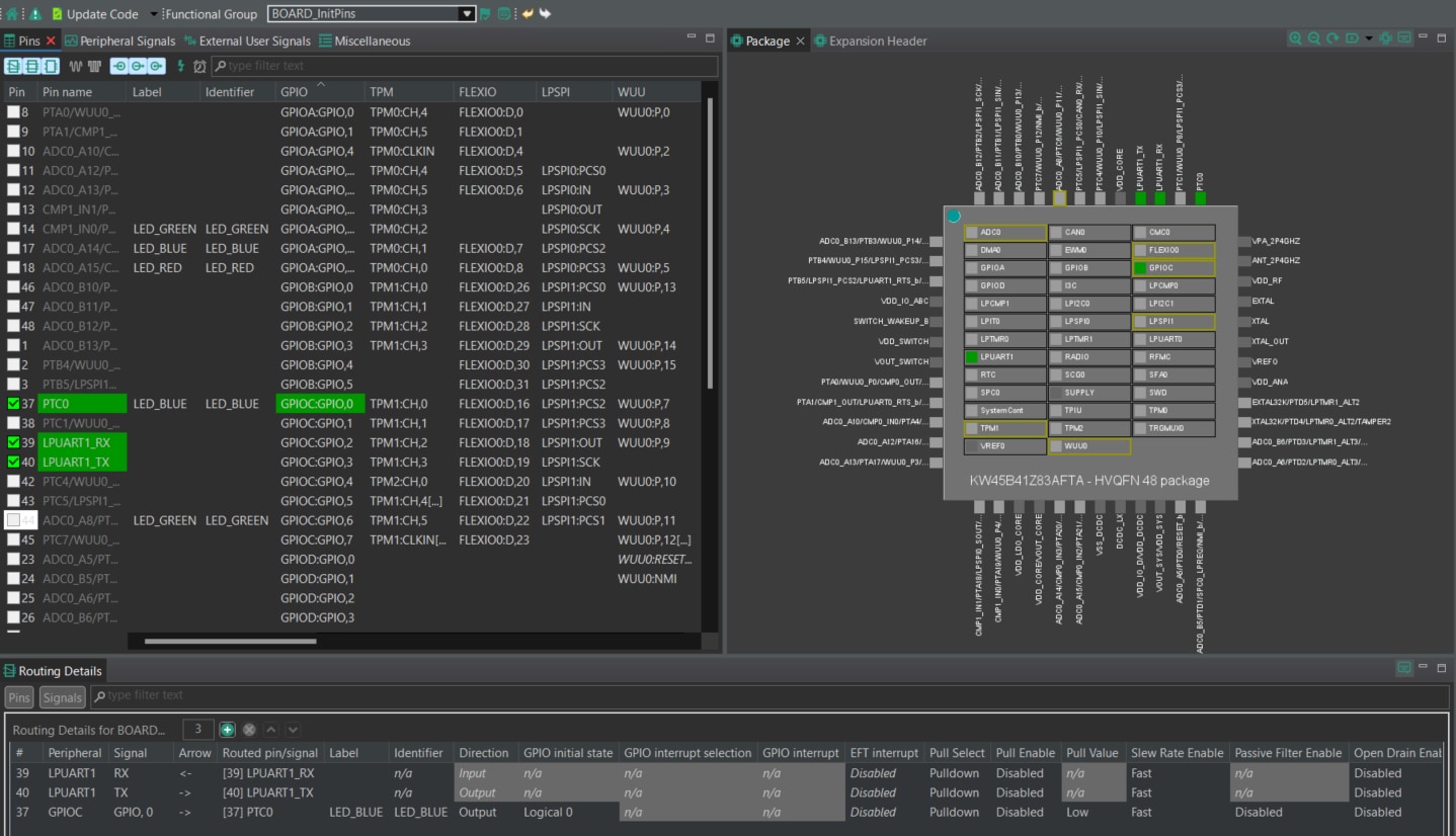
4.3 使用引脚工具修改LED路由的引脚
- 在“引脚”视图中,取消选中“显示专用引脚”和“显示未路由的引脚”复选框,仅查看已路由的引脚。已路由的引脚在引脚名称旁留有一个绿色勾选框。为每个已路由引脚所选的功能以绿色突出显示
- 在当前配置中,PTC0 (LEB_BLUE)被路由为输出。添加引脚配置,以启用绿色LED
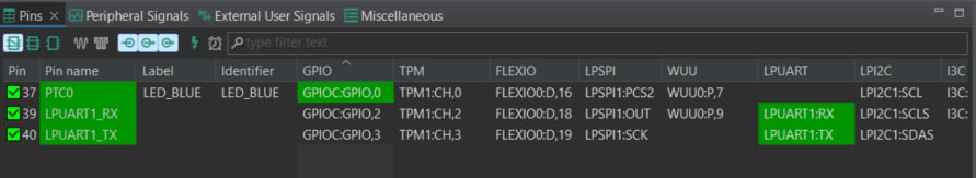
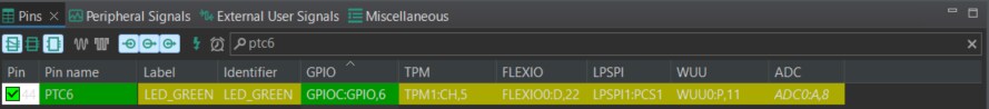
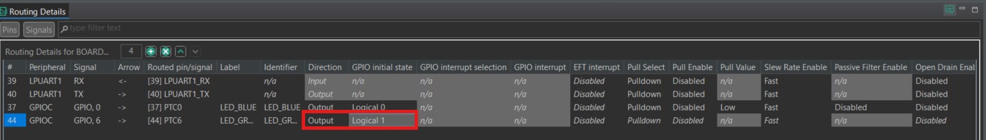
- 选择“显示未路由的引脚”以查看其他选项。要启用绿色LED,请搜索PTC6,并在GPIO列中选择GPIO6。对任何同步路由消息均选择“否”
- 接下来,在“路由详情”窗口中将GPIO引脚配置为输出,将逻辑1配置为GPIO初始状态
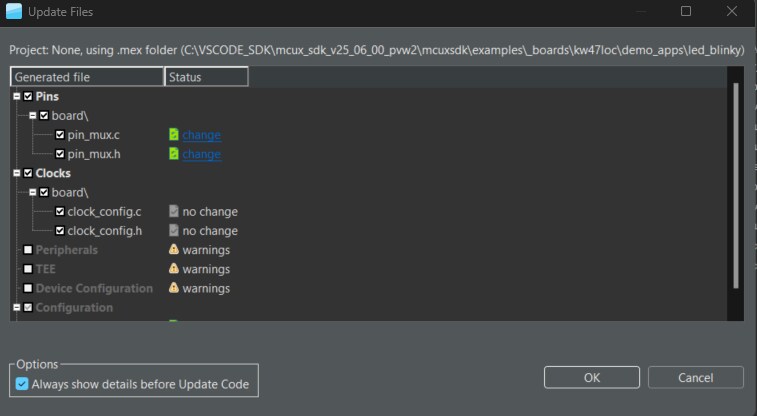
- 现在是时候导出由引脚工具生成的最新pin_mux.c和pin_mux.h文件,将这些更改实施到项目中。点击菜单栏中的“更新项目”
- 弹出的窗口将显示正在更改的文件。点击“确定”将新文件覆盖到项目中
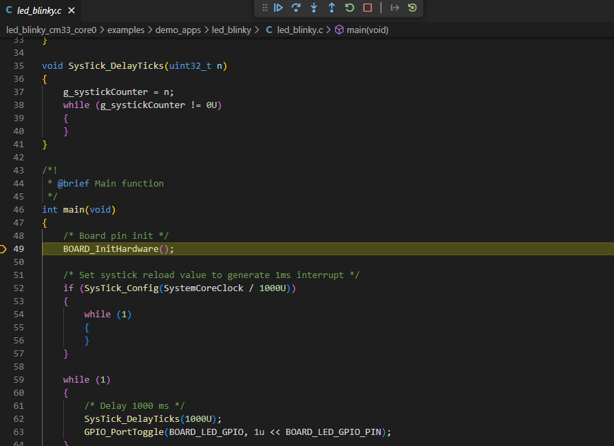
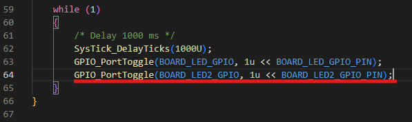
- 给示例添加一些额外的代码。打开led_blinky.c文件,并添加以下行以切换绿色LED
- 按照上一节所述构建并下载项目
- 运行应用。现在应该能看到绿色和蓝色LED交替闪烁
- 终止调试会话

5. MCUXpresso Developer Experience(MCUXpresso开发人员体验)
请查看以下各个章节,了解我们为灵活的原型设计和开发提供的生态合作体系。在下面的视频中,我们将向您介绍FRDM平台、功能齐全的EVK和兼容的扩展板。另外,我们还将带您浏览Application Code Hub (应用代码中心)页面,让您了解许多通过恩智浦Github提供的应用示例。
5.1 FRDM平台、功能齐全的EVK和扩展板
为了加速平台原型制作,我们提供了低成本FRDM平台和功能齐全的评估套件。
FRDM开发板具有标准规格和接头,便于连接MCU的输入/输出端口,并内置了MCU-Link调试器,带有USB-C线。我们的评估套件功能齐全,包括扩展的输入/输出和接口访问,支持通过WiFi和其他MCU-Link功能进行扩展。此外,还有许多兼容的Click板和/或Arduino扩展板。对于那些支持Open CMSIS Pack的平台,可以在ACH上找到一些示例,但如果没有,许多都可以通过I2C、SPI和UART等串行接口来使用,我们在MCUXpresso SDK中提供了相应的驱动程序和示例。
5.2 Application Code Hub (应用代码中心)
Application Code Hub (应用代码中心)为开发人员提供了一个交互式仪表板来快速定位软件,进一步增强了MCUXpresso Developer Experience。立即访问ACH ,开始探索及发现新的交互式Application Code Hub(应用代码中心)的更多细节和优势。
可从Application Code Hub (应用代码中心)访问的软件位于恩智浦GitHub存储库 ,因此可以直接从该位置轻松访问和克隆。
5.3 演示纵览
以下演示引导我们使用基于FRDM平台的系统从ACH导入一个项目,该系统具有电机控制扩展板和低成本LCD。尽管您的评估板可能与该系统有所不同,但以下步骤是通用的,适用于所有支持的平台。