i.MX 93 Auto EVK快速入门
本文档内容
-
开箱即用
-
获取软件
-
构建、运行
-
Developer Experience (开发人员体验)
1. 开箱即用
下面描述了启动i.MX 93 Auto EVK的步骤。
开发套件包含:
- 配备恩智浦Wi-Fi® 6/BLE AW611的i.MX 93 Auto EVK板
- 电源:12V/8.3A通用电源
- 线缆:组装,USB 2.0,Type-C公头转Type-A公头
- 软件:在eMMC中烧写的Linux BSP镜像
- 快速入门指南
按照演示视频所示步骤,采用i.MX93 Auto EVK开始开发应用。如需了解更多信息,请访问i.MX 93应用处理器文档。
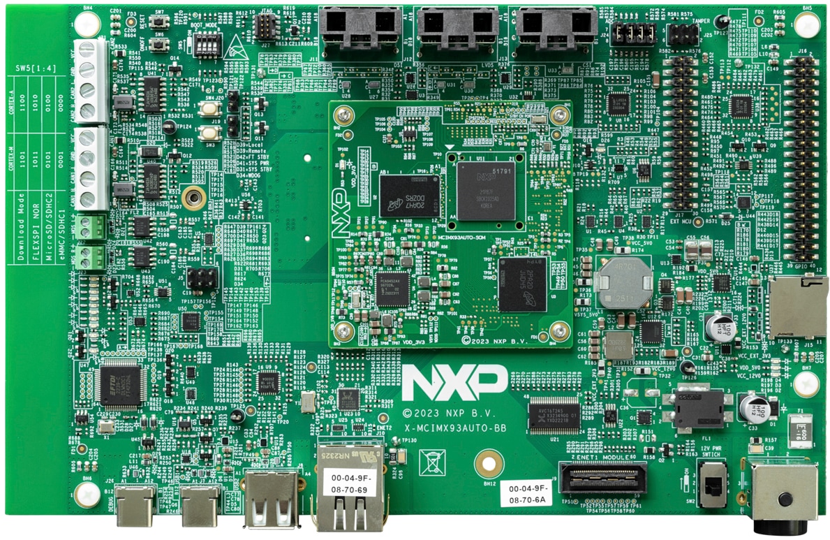
1.1 熟悉板
1.2 从eMMC启动
i.MX 93 Auto EVK配备一个预构建的恩智浦Linux二进制演示镜像,烧写在eMMC上。无需修改内部的二进制文件,从eMMC启动将提供具有某些功能的默认系统,在Linux上构建其他应用。
如需了解有关恩智浦Embedded Linux®、MCUXpresso SDK的更多详情,请继续阅读后续章节。
1.3 连接USB调试线缆
将随附的USB Type-C线缆连接到调试UART端口J26,然后将线缆的另一端连接到主机。
主机上将显示四个UART连接。 第三个端口用于A55内核,第四个端口用于M33内核系统调试。如果您不熟悉终端应用,请先查看以下某个教程,再继续步骤1.4:Minicom教程、Tera Term教程、PuTTY教程。
1.4 连接HDMI线缆
要查看镜像二进制文件提供的用户界面,请使用IMX-MIPI-HDMI线通过MIPI-DSI J11连接显示器。
1.5 启动开关设置
SW5[1-4] 是启动配置开关。默认情况下,启动设备是eMMC/uSDHC1。
| 启动模式 | 启动内核 | SW5-4 | SW5-3 | SW5-2 | SW5-1 |
|---|---|---|---|---|---|
| 从内部熔丝 | Cortex-A55 | 0 | 0 | 0 | 1 |
| 串行下载器 | Cortex-A55 | 0 | 0 | 1 | 1 |
| USDHC1 8位eMMC 5.1 | Cortex-A55 | 0 | 0 | 0 | 0 |
| USDHC2 4位SD3.0 | Cortex-A55 | 0 | 0 | 1 | 0 |
| FlexSPI Serial NOR | Cortex-A55 | 0 | 1 | 0 | 1 |
| FlexSPI Serial NAND 2K页面 | Cortex-A55 | 0 | 1 | 1 | 1 |
| 无限循环 | Cortex-A55 | 0 | 1 | 0 | 0 |
| 测试模式 | Cortex-A55 | 0 | 1 | 1 | 0 |
| 从内部熔丝 | Cortex-M33 | 1 | 0 | 0 | 1 |
| 串行下载器 | Cortex-M33 | 1 | 0 | 1 | 1 |
| USDHC1 8位eMMC 5.1 | Cortex-M33 | 1 | 0 | 0 | 0 |
| USDHC2 4位SD3.0 | Cortex-M33 | 1 | 0 | 1 | 0 |
| FlexSPI Serial NOR | Cortex-M33 | 1 | 1 | 0 | 1 |
| FlexSPI Serial NAND 2K页面 | Cortex-M33 | 1 | 1 | 1 | 1 |
| 无限循环 | Cortex-M33 | 1 | 1 | 0 | 0 |
| 测试模式 | Cortex-M33 | 1 | 1 | 1 | 0 |
1.6 板启动
将电源线插入电源连接器(J6)。拨动开关(SW2)给板上电。
处理器开始执行片上ROM的代码。使用默认启动开关设置,代码读取熔丝,定义可能有可启动镜像的介质。找到可启动镜像后,U-Boot执行应自动开始。
信息在Arm® Cortex®-A55的串行控制台中打印。如果不停止U-boot流程,就会继续启动内核。
恭喜,Linux启动已完成。
当板启动时,您会看到显示器的左上角出现两只企鹅,然后在左上角看到Linux终端图标,在右上角看到定时器。恭喜,已顺利启动并运行。
2. 获取软件
本部分仅适用于将Linux®操作系统加载到板的情况。
i.MX Linux板级支持包(BSP)是一系列二进制文件、源代码和支持文件,可用来启动特定i.MX开发平台上的Embedded Linux镜像。
当前Linux二进制演示文件版本请参见Linux下载页面。i.MX软件和开发工具的Linux部分中的i.MX Linux文档包提供其他文档。
2.1 概述
Linux操作系统内核在i.MX板上启动前,需要将Linux加载到启动设备(SD卡、eMMC等),而启动开关需要设置为启动此设备。
为不同的板和启动设备下载Linux BSP镜像有多种方法。
本入门指南仅概述了将Linux BSP镜像烧写到SD卡的几种方法。经验丰富的Linux开发人员可根据需要探究其他选项。
2.2 下载恩智浦Linux BSP预构建镜像
i.MX 93 Auto EVK最新的预构建镜像可参见Linux最新版本的Linux下载页面。
预构建的恩智浦Linux二进制演示镜像提供典型系统和基本的功能集,用于使用和评估处理器。无需修改系统,用户就可以评估硬件接口、测试SoC功能并运行用户空间应用。
当需要更多灵活性时,SD卡可逐一与单个组件(引导加载程序、内核、dtb文件和rootfs文件)一起加载,或者可加载*wic镜像,并且特定组件可以覆盖单个部件。
2.3 使用Universal Update Utility (UUU)烧写恩智浦Linux BSP镜像
除了“开箱即用”章节的连接外,使用USB线缆将USB1连接到主机。
给板断电。参考“启动开关设置”章节,配置板在串行下载协议(SDP)模式启动。
根据主机中使用的操作系统,将Linux BSP镜像传输到启动设备的方式可能会有所不同。从下面的选项中进行选择,获取详细指导:
Linux®
1. 在Linux Distro上安装UUU
如需下载最新的stable文件,请访问UUU GitHub页面。如需有关UUU的进一步帮助,请参阅本详细教程。
uuulibusb1(通过apt-get或任何其它资源包管理器)
2 将恩智浦Linux BSP镜像烧写到板上
在默认情况下,本流程将镜像烧写到eMMC闪存中。查看UUU GitHub页面 ,了解如何将镜像烧写到其他设备。
打开命令提示应用,转到uuu.exe文件及i.MX 93 Auto EVK最新Linux版本所在目录。
uuu.exe -b emmc_all imx-boot-imx93-14x14-lpddr4x-evk-sd.bin-flash_singleboot imx-image-full-imx93evk.wic 确认i.MX93 Auto EVK启动模式已切换至串行下载模式,然后打开板,uuu将开始将镜像烧写到SD卡。
完成后,给板和终端断电。如需获得关于配置板从eMMC启动的进一步帮助,请参阅启动开关设置。
Windows®
1. 在Linux Distro上安装UUU
如需下载最新的stable文件,请访问UUU GitHub页面。有关UUU的详细教程,请访问mfgtools。
uuulibusb1(通过apt-get或任何其它资源包管理器)
2 将恩智浦Linux BSP镜像烧写到板上
在默认情况下,本流程将镜像烧写到SD卡闪存中。查看uuu GitHub页面 ,了解如何将镜像烧写到其他设备。
打开终端应用,将目录更改为uuu及i.MX 93 Auto EVK最新Linux版本所在位置。向UUU文件添加执行权限并执行。Uuu等待USB设备连接
$ chmod a+x uuu sudo ./uuu -b emmc_all imx-boot-imx93-14x14-lpddr4x-evk-sd.bin-flash_singleboot imx-image-full-imx93evk.wic确认i.MX93 Auto EVK启动模式已切换至串行下载模式,然后打开板,uuu将开始将镜像烧写到SD卡。
完成后,给板和终端断电。如需获得关于配置板从eMMC启动的进一步帮助,请参阅启动开关设置。
3. 构建、运行
本节简要介绍了如何为i.MX93 Auto EVK构建Yocto BSP镜像。
MCUXpresso软件开发套件(MCUXpresso SDK)提供了在i.MX 93 M33内核中执行的全部软件源代码。如果您此时不想在i.MX 93上启用Arm® Cortex®-M33,则可跳过第3.2和3.3节。
3.1 i.MX93 Auto EVK Yocto BSP
要从源代码构建i.MX93 Auto EVK镜像,请先查阅《i.MX Yocto Project用户指南》,熟悉Yocto Project和Yocto Build。然后,请按照以下步骤为i.MX93 Auto EVK构建镜像。
- 下载i.MX SW 2025 Q1 BSP版本:
$ repo init -u https://github.com/nxp-imx/imx-manifest -b imx-linux-styhead -m imx-6.12.3-1.0.0.xml $ repo sync - Yocto Project设置:
$ DISTRO=fsl-imx-xwayland MACHINE=imx93-14x14-lpddr4x-evk source imx-setup-release.sh -b build-xwayland - 构建镜像:
$ bitbake imx-image-full - 将镜像烧写到SD卡:
$ imx-image-full-imx93-14x14-lpddr4x.rootfs.wic.zst | sudo dd of=/dev/sdx bs=1M && sync $ uuu -b sd_all imx-image-full-imx93-14x14-lpddr4x.rootfs.wic.zst - 或使用uuu,将镜像烧写到SD卡:
$ uuu -b sd_all imx-image-full-imx93-14x14-lpddr4x.rootfs.wic.zst - Change boot switch
SW5[1:4]to "0100" to select SD card boot, insert the SD card and power up the i.MX 93 Auto EVK.
3.2 MCUXpresso SDK概述
The MCUXpresso SDK is designed for the development of embedded applications for Cortex®-M33 standalone or collaborative use with the A cores. Along with the peripheral drivers, the MCUXpresso SDK provides an extensive and rich set of example applications covering everything from basic peripheral use case examples to demo applications. The MCUXpresso SDK also contains RTOS kernels and device stack and various other middleware to support rapid development.
This guide shows how to run the m33_image.bin demo provided by the release. For detailed information on MCUXpresso SDK and how to build and deploy custom demos, please visit MCUXpresso SDK site.
3.3 采用U-Boot运行应用
This section describes how to run applications using an SD card and pre-built U-Boot image for i.MX processor.
- Following the steps from section Get Software, prepare an SD card with a pre-built U-Boot + Linux image from the Linux BSP package for the i.MX 93 processor. If you have already loaded the SD card with a Linux image, you can skip this step
- Insert the SD card in the host computer (Linux or Windows) and copy the application image (for example
m33_image.bin) to the FAT partition of the SD card - Safely remove the SD card from the PC
- Insert the SD card to the target board. Make sure to use the default boot SD slot and double check the Boot Switch Setup guide
- Connect the DEBUG UART connector on the board to the PC through a USB cable. The Windows OS installs the USB driver automatically, and the Ubuntu OS will find the serial devices as well. See Connect USB Debug Cable section for more instructions on serial communication applications. Open a second terminal on the i.MX93 Auto EVK board's fourth enumerated serial port
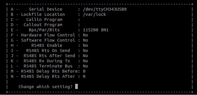
- This is the Cortex-M33's serial console. Set the speed to 115200 bit/s, data bits 8, 1 stop bit (115200, 8N1), no parity Power up the board and stop the boot process by pressing any key before the U-Boot countdown reaches zero. At the U-Boot prompt on the first terminal, type the following commands
=> fatload mmc 1:1 0x80000000 m33_image.bin
=> cp.b 0x80000000 0x201e0000 0x10000
=> bootaux 0x1ffe0000 0
These commands copy the image file from the partition of the SD card into the Cortex-M33's TCM and releases the Cortex-M33 from reset.
4. Developer Experience (开发人员体验)
为了帮助各种技能水平的用户加速开发,恩智浦提供了丰富的示例应用,以展示该平台的各种功能和性能。
4.1 Application Code Hub (应用代码中心)
The Application Code Hub (ACH) repository enables engineers to easily find microcontroller and processor software examples, code snippets, application software packs and demos developed by NXP in-house experts. This space provides a quick, easy and consistent way to find microcontroller and processor applications.
ACH provides filter and search options to quickly find specific applications. With the support of Git capabilities, there is an easy way to import and use applications within user’s development environments.
To learn more details of ACH, please visit this link.
4.2 面向i.MX应用处理器的GoPoint
The GoPoint for i.MX Application Processors is a user-friendly application that launches pre-built applications packed with the Linux BSP, giving users an excellent out-of-the-box experience and hands-on experience with i.MX SoC's capabilities. GoPoint highlights advanced features while providing practical solutions for implementation, with source code and build recipes for the applications provided in GitHub.
To learn more details of GoPoint, please visit this link.
Minicom Tutorial
Serial Communication Console Setup
On the command prompt of the Linux host machine, run the following command to determine the port number:
$ ls /dev/ttyUSB*较小编号适用于Arm® Cortex®-A55内核,较大编号适用于Arm Cortex-M33内核。
Minicom
使用以下命令安装和运行串行通信程序(以minicom为例):
- 使用Ubuntu包管理器安装Minicom。
- 使用先前确定的端口号通过控制台窗口启动Minicom
- 配置Minicom,如图所示
- 下一步是连接HDMI线
$ sudo apt-get install minicom$ sudo minicom /dev/ttyUSB* -sTera Term Tutorial
Serial Communication Console Setup
i.MX 93上的FTDI USB串行芯片将枚举4个串行端口。假设端口为COM11、COM12、COM13、COM14。第三个端口(COM13)用于从Arm® Cortex®-A55内核进行串行控制台通信,第四个端口(COM14)用于Arm Cortex-M33内核。串行转USB驱动程序请参见FTD芯片驱动 。
Tera Term
它是一款开源终端仿真应用。此程序显示从恩智浦开发平台的虚拟串行端口发送的信息。
- 下载Tera Term。下载完成后,运行安装程序,然后返回到该页面继续操作。
- 启动TeraTerm。首次启动时,会显示以下对话。选择串行选项。假设已插入板,列表中会自动填充一个COM端口
- 配置串行端口设置(使用之前确定的COM端口号),波特率为115200,数据位为8,无奇偶校验位,停止位为1。要进行此操作,进入Setup→Serial Port(设置→串行端口)并更改设置
- 确认连接已打开。如已连接,Tera Term将在标题栏中显示以下内容
- 下一步是连接HDMI线
Putty Tutorial
Serial Communication Console Setup
i.MX 93上的FTDI USB串行芯片将枚举4个串行端口。假设端口为COM11、COM12、COM13、COM14。第三个端口(COM13)用于从Arm® Cortex®-A55内核进行串行控制台通信,第四个端口(COM14)用于Arm Cortex-M33内核。串行转USB驱动程序请参见FTD芯片驱动 。
PuTTY是一款广受欢迎的终端仿真应用。此程序显示从恩智浦开发平台的虚拟串行端口发送的信息。
- 下载PuTTY下载完成后,运行安装程序,然后返回到该页面继续操作。
- 启动PuTTY,可双击下载的*.exe文件或从开始菜单启动,具体取决于您所选的下载类型。
- 配置在启动的窗口中进行。选择Serial单选按钮并输入之前确定的COM端口号。还要输入波特率,在本例中,为115200
- 点击“Open”(打开),打开串行连接。假设板已连接,并已输入正确的COM端口,此终端窗口会打开。如果配置不正确,PuTTY将会发出提示
- 下一步是连接HDMI线