FRDM-MCXA266快速入门
本文档内容
-
开箱即用
-
获取软件
-
构建并运行
-
创建
-
5. MCUXpresso Developer Experience(MCUXpresso开发人员体验)
1. 开箱即用
现在开始试用FRDM板!您可以选择观看短片中的操作顺序或遵循下列详细操作步骤。
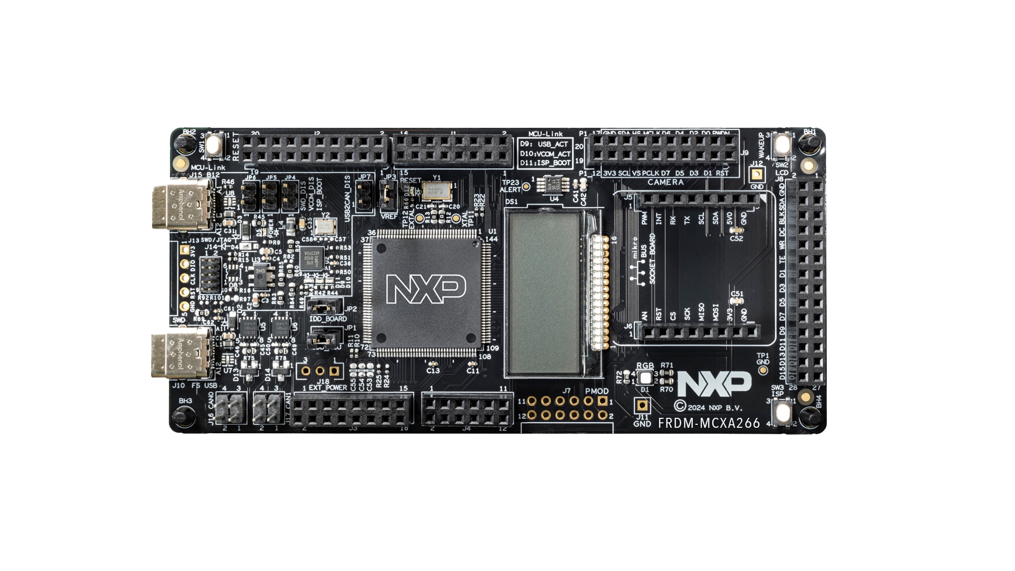
1.1 熟悉板
FRDM-MCXA266板预编程了一个带LED闪烁的演示程序。这是一个健全性检查,用来检验设备是否能按照预期正常工作。
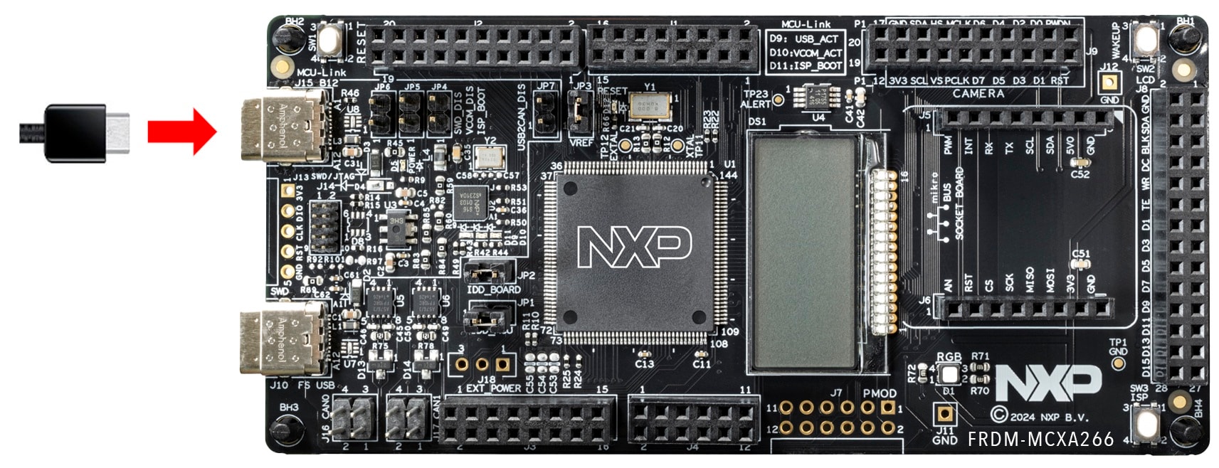
1.2 连接板
使用type-C USB线将连接器J15连接至主机或电源,给板上电并运行演示程序。这时,您应该看到RGB LED指示灯以稳定的节奏闪烁。
2. 获取软件
2.1 安装工具链
恩智浦提供名为MCUXpresso IDE的附赠工具链。请下载MCUXpresso v25.6.136及以上版本。
需要帮助选择?
了解如何为主机安装VS Code,参考以下教程。
想使用不同的工具链?
如果需要帮助选择,请浏览MCUXpresso软件和工具套件。
MCUXpresso SDK支持IAR 、KEIL 和命令行GCC 等其他工具。
2.2 采用MCUXpresso SDK,快速开始设计
MCUXpresso SDK为免费附赠,包含所有硬件抽象和外设驱动软件的完整源代码,根据宽松的开源许可提供。您可以直接从MCUXpresso SDK网站 安装MCUXpresso SDK。点击下面的按钮,打开该板的SDK builder。

2.3 MCUXpresso配置工具
MCUXpresso配置工具是一套集成的配置工具,可指导用户创建新的MCUXpresso SDK项目,还提供引脚和时钟工具,以生成支持定制板的初始化C代码。它完全集成到MCUXpresso IDE中,如果使用其他IDE,则可以将其作为单独的工具。
点击下面的“Get MCUXpresso Config Tools”(获取MCUXpresso配置工具)按钮,获取配置工具安装程序。
2.4 编程和配置工具
MCUXpresso安全配置(SEC)工具是一款基于GUI的应用,用于简化在恩智浦MCU上生成和配置可启动的可执行文件。建议所有用户首先使用MCUXpresso安全配置(SEC)工具进行试运行和大规模生产。它支持在量产阶段对恩智浦微控制器进行安全编程和设备配置。
下载该工具后,可在“帮助”选项卡下找到用户指南。接下来,按照“处理器特定工作流程”一章中针对您的板的说明进行操作。

3. 构建并运行
如果您对其中的一个或几个演示应用或驱动程序示例感兴趣,也许想了解如何自己完成构建和调试。MCUXpresso SDK快速入门指南按步骤介绍了如何轻松地为SDK支持的所有工具链配置、构建和调试演示。
3.1 使用MCUXpresso IDE构建和烧写应用
以下步骤将指导您使用Cortex-M33应用的MCUXpresso IDE来运行hello_world演示应用。MCUXpresso IDE安装和MCXA系列的SDK可在本快速入门指南的“获取软件”部分找到。
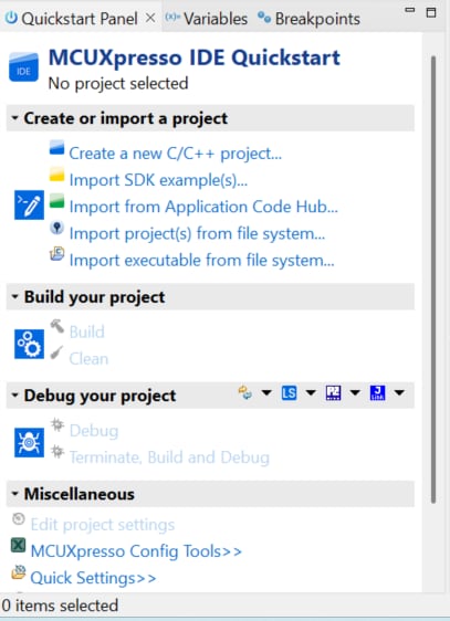
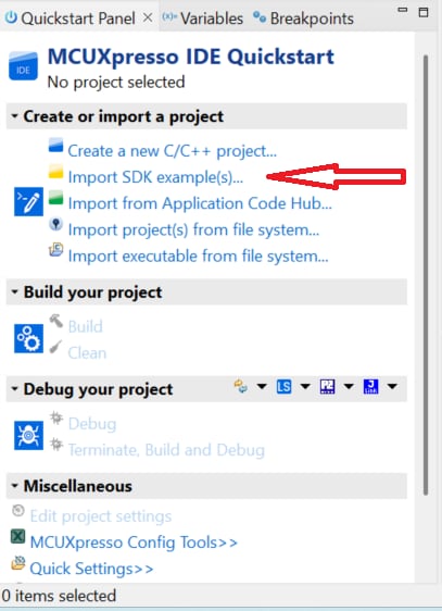
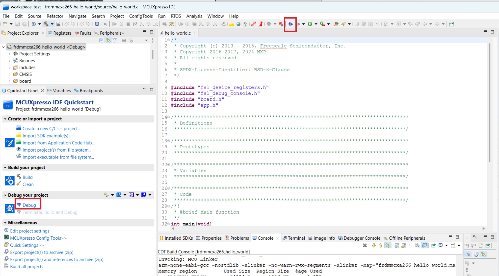
在左下角找到“快速启动面板”
- FRDM-MCXA266 SW快速启动面板
- 然后点击“导入SDK示例”
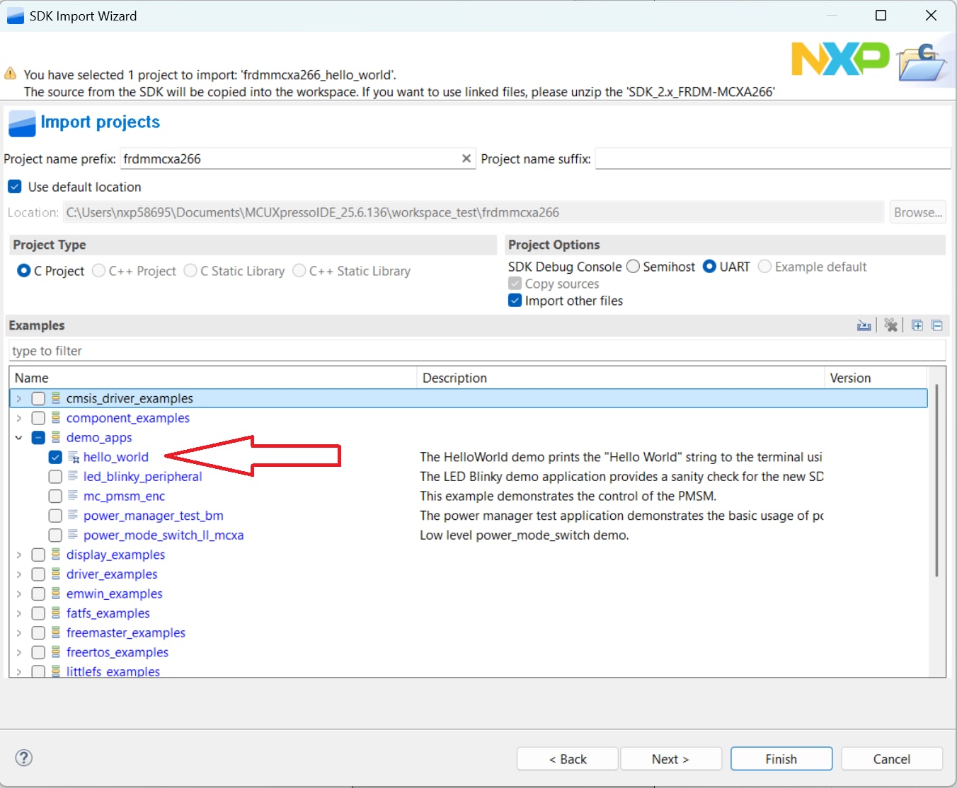
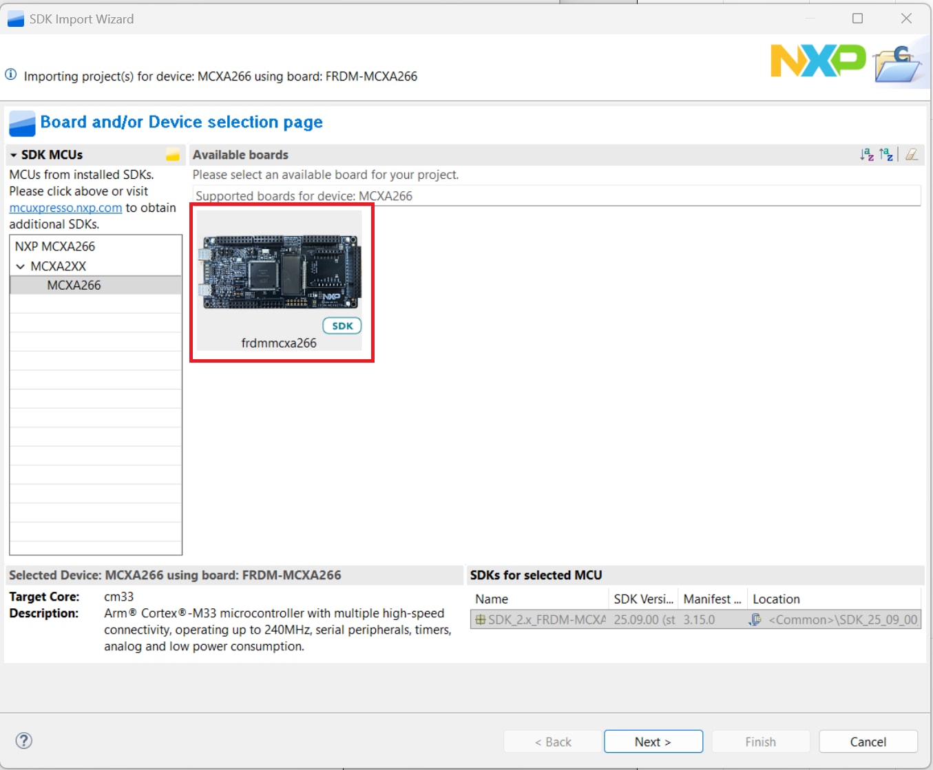
- 点击FRDM MCX-A266板,选择一个可以在该板上运行的示例,然后点击“下一步”
- 使用箭头按钮来展开demo_apps类别,然后点击hello_world旁边的复选框来选择该项目。要使用UART进行打印(而不是默认的半主机),请在项目选项下选择“UART as the SDK Debug Console(UART作为SDK调试控制台)”复选框。再点击“完成”
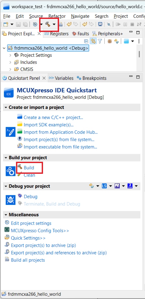
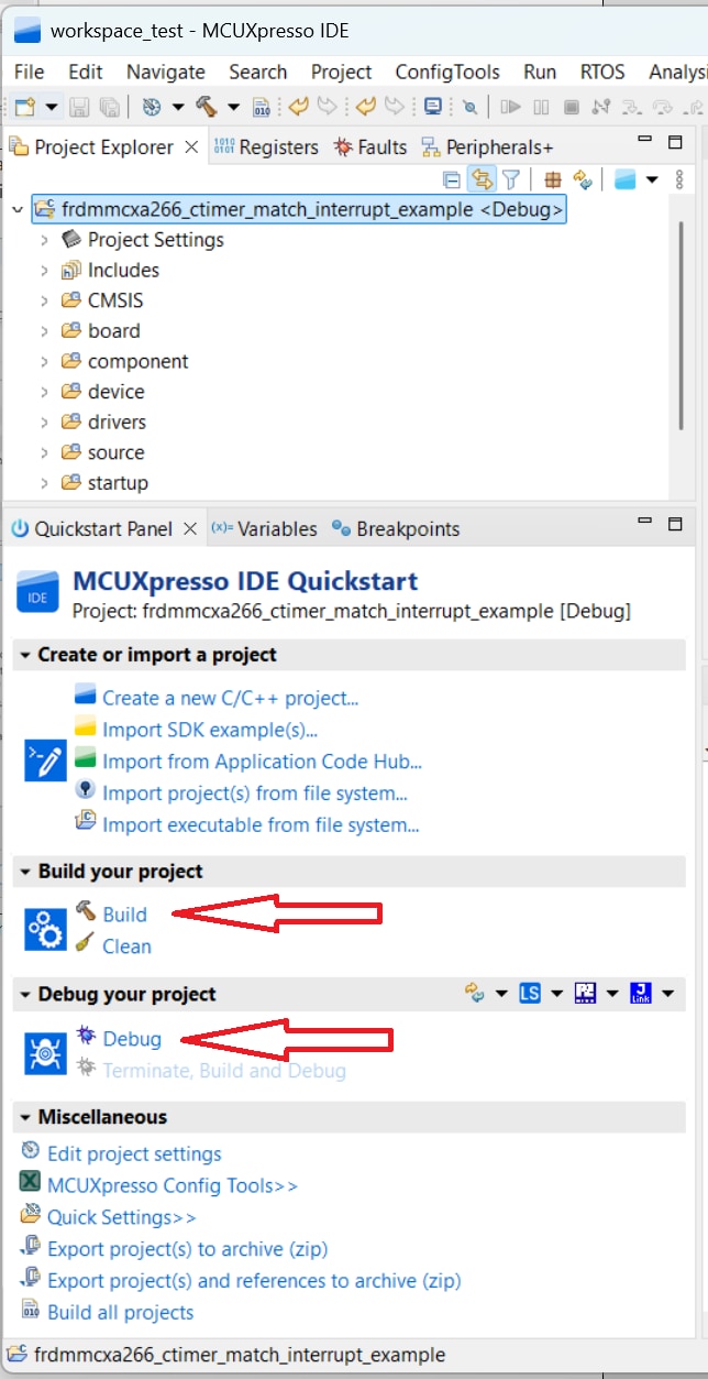
- 选择要构建的项目,然后点击上方快捷方式中的“Build(构建)”图标,或者在快速启动面板中点击“Build(构建)”
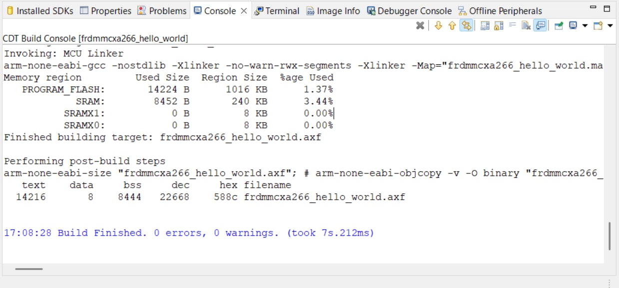
- 项目应该能够在控制台中构建完成,不会出现错误或警告
- 使用与
J15'MCU-LINK'端口连接的Micro USB将板连接到计算机 - 点击上方的“Debug(调试)”图标,或者在快速启动面板中点击“Debug(调试)”,将应用下载到板上
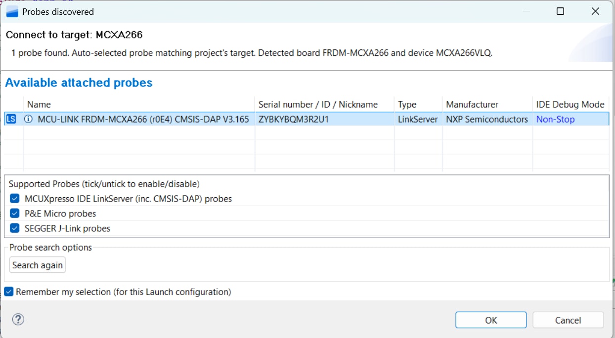
- 选择MCU-Link CMSIS-DAP硬件调试器
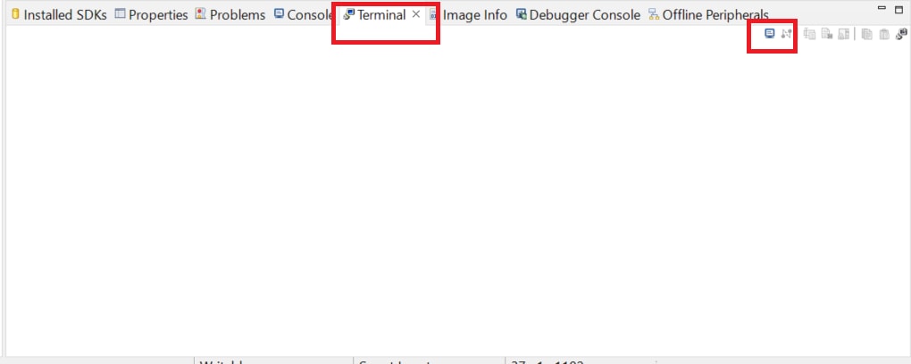
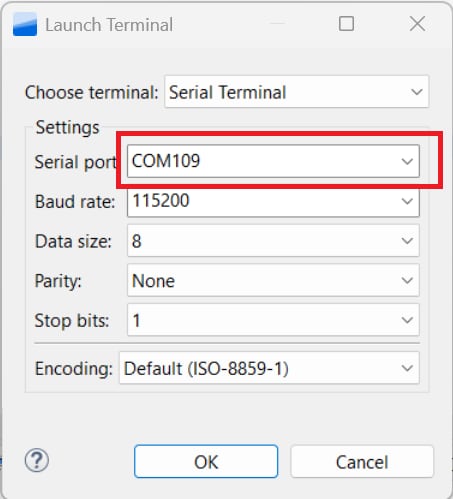
- 打开一个串行终端,以便查看应用的输出。选择“Terminal(终端)”窗口,然后点击“New Terminal(新建终端)”图标
- 选择“Serial Terminal(串行终端)”,然后对UART进行设置:波特率为115200,数据位为8,无奇偶校验位,停止位为1。按“确定”
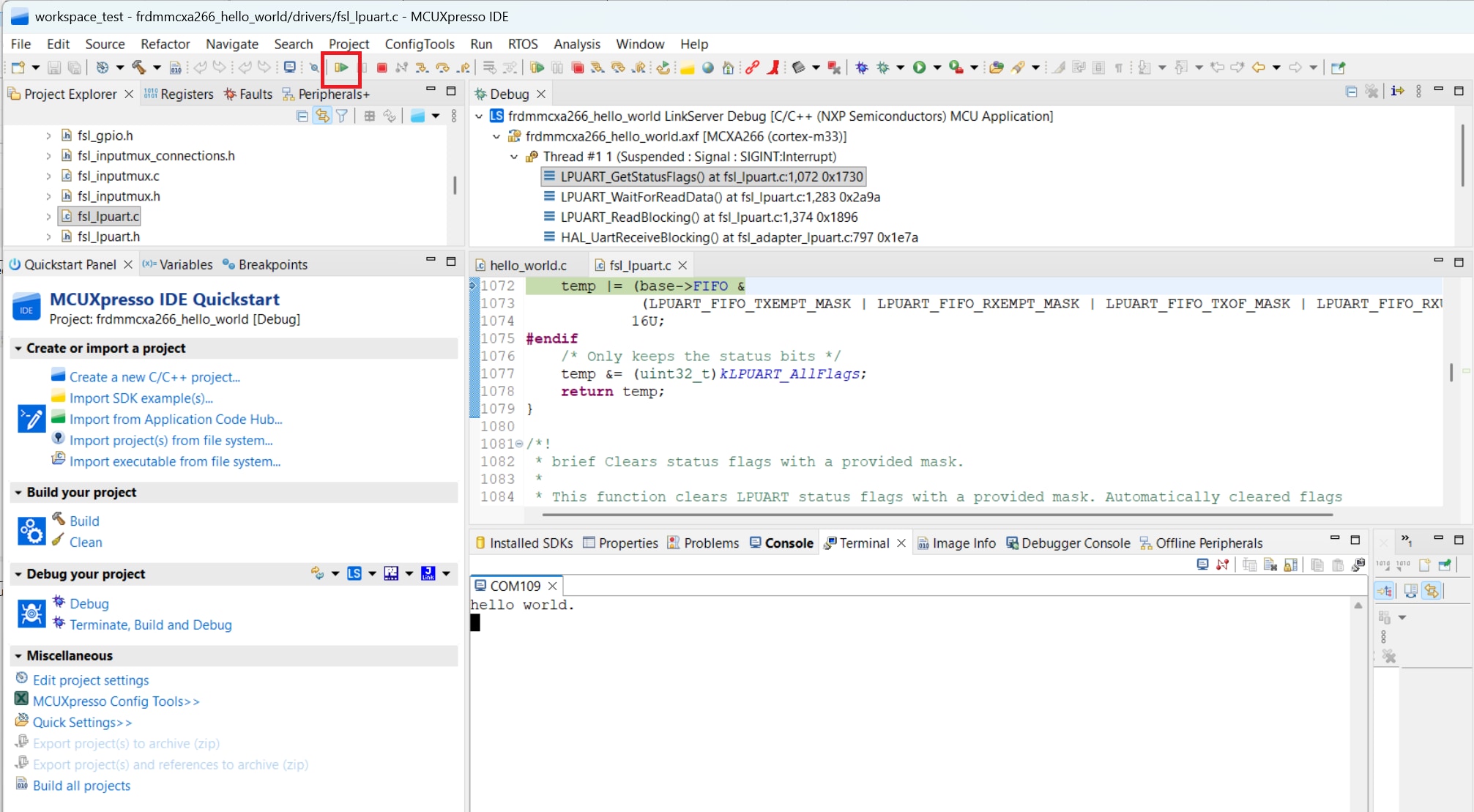
- 点击“Run(运行)”图标,运行应用。 在终端上查看输出结果

3.2 使用其他工具链构建和烧写应用
MCUXpresso for Visual Studio Code (VS Code)为嵌入式开发人员优化了代码编辑和开发体验。了解如何使用VS Code构建和烧写应用。
想使用其他工具链?
此演示也适用于IAR和Keil。
4. 创建
4.1 从MCUXpresso IDE克隆示例项目
遵循以下步骤完成通用输出的操作。这个例子使用CTimer来产生PWM信号,并在两个LED之间切换。
- 在左下角找到快速启动面板,然后点击“导入SDK示例”
- 点击FRDM-MCXA266板,选择一个可以在该板上运行的示例,然后点击“下一步”
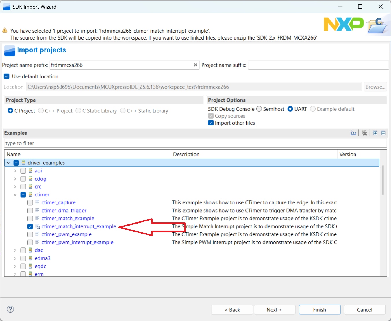
- 使用箭头按钮展开driver_examples类别,然后展开CTimer示例,并点击ctimer_match_interrupt_example旁的复选框选择它。要使用UART进行打印(而不是默认的半主机),请在项目选项下选择“UART as the SDK Debug Console(UART作为SDK调试控制台)”复选框。然后点击“完成”
- 点击“Project Explorer View(项目资源管理器视图)”中的frdmmcxa266_ctimer_match_interrupt_example项目,并如上述章节所述构建、编译和运行演示
- 您会看到绿色和红色LED指示灯来回切换
- 终止调试会话

4.2 使用MCUXpresso配置工具为第三方IDE克隆示例项目
遵循以下步骤完成通用输出的操作。该示例创建了一个CTimer,用于使红色和绿色LED来回切换。
- 打开MCUXpresso配置工具
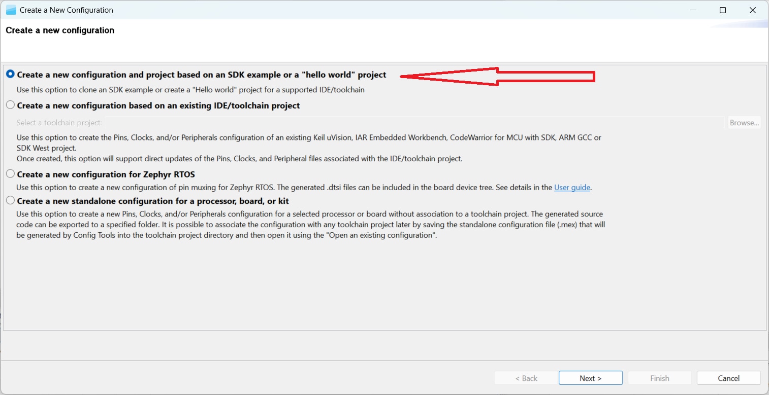
- 在出现的向导中,选择“基于SDK示例或hello word项目创建新配置”单选按钮,然后点击“下一步”
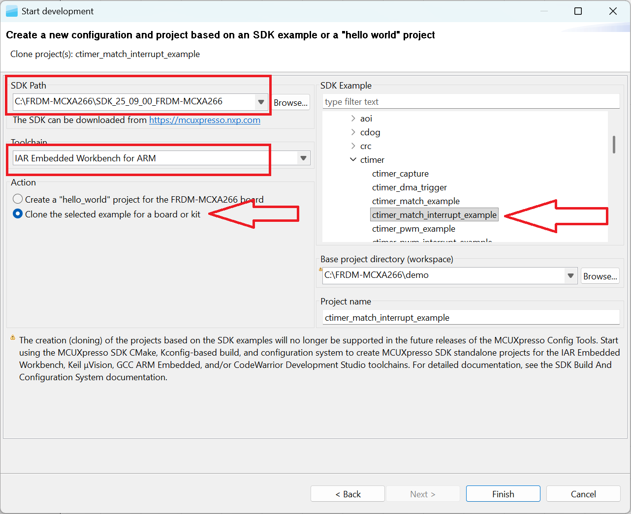
- 在下一个界面,选择MCUXpresso SDK的位置。必须事先解压SDK包。然后选择正在使用的IDE。请注意,只有在构建SDK时,在线SDK构建工具中所选的IDE才可用。点击“为板或套件克隆所选示例”。然后选择要克隆的项目。对于本示例,要使用CTimer match interrupt项目。可以在筛选框中输入"ctimer",然后选择ctimer_match_interrupt_example示例项目,进行筛选。然后,还可以指定克隆项目的位置和名称。再点击“完成”
- 克隆后,进入所选择的目录,并打开IDE的项目。导入、编译和运行项目,如前几节所述
- 您会看到红色和绿色LED指示灯来回切换
- 终止调试会话
4.3 使用MCUXpresso IDE引脚工具
注:以前,您必须像上一步一样克隆SDK项目。
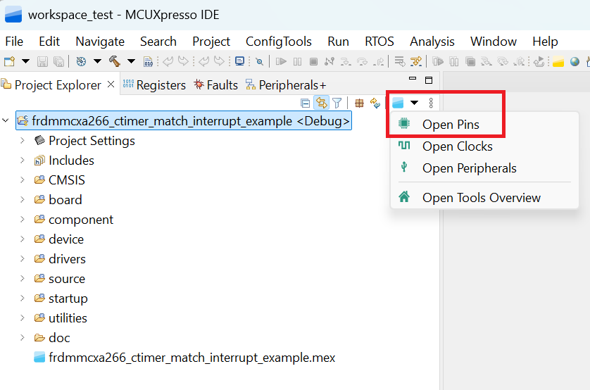
- 选择文件资源管理器窗口右上角的“ConfigTools”(配置工具),然后选择“Open Pins”(打开引脚)来打开引脚工具
- 引脚工具现在应该显示CTimer项目的引脚配置
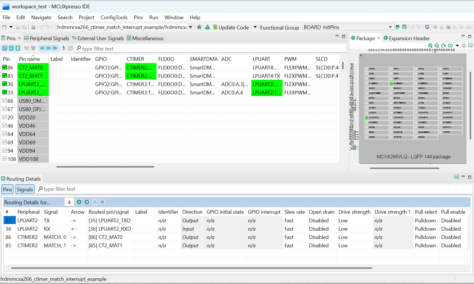
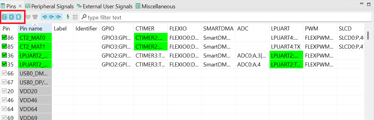
4.4 使用引脚工具修改LED布线的引脚
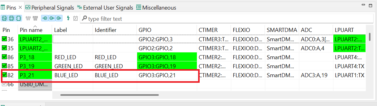
- 我们将在指南的剩余部分使用MCUXpresso IDE,但在其他第三方IDE的MCUXpresso配置工具中可以完成相同的步骤。在引脚视图中,取消选中“显示专用引脚”和“显示未路由引脚”复选框,以仅查看已路由引脚。已路由引脚在引脚名称旁留有一个绿色勾选框。为每个已路由引脚所选的功能以绿色突出显示
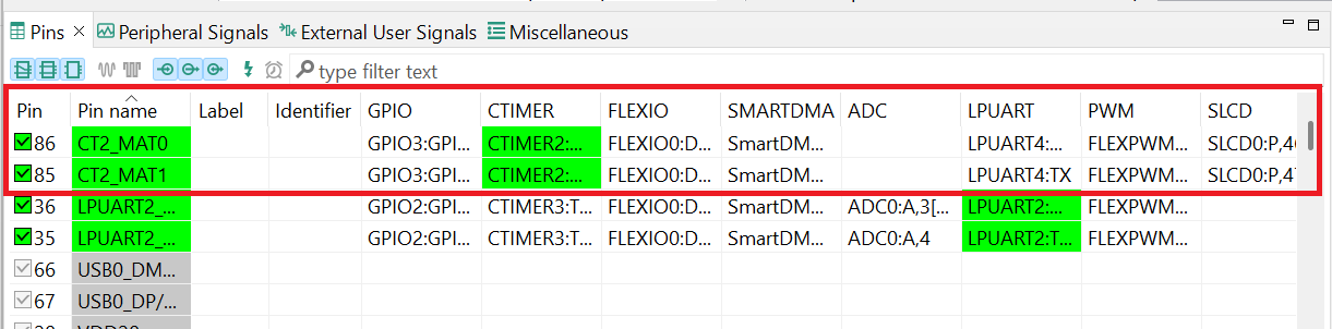
- 在当前配置中,PIO3_18和PIO3_19被路由为CTimer的输出。我们更改引脚配置,并添加蓝色LED
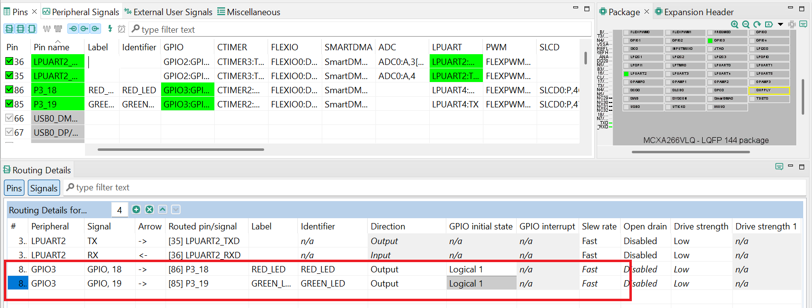
- 将CTimer输出引脚PIO3_18改为GPIO,并输出逻辑1以禁用红色LED
- 选择“显示未路由引脚”以查看其他选项。要启用蓝色LED,请搜索
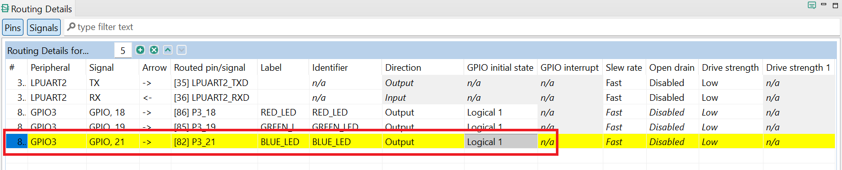
P3_21,并在GPIO列中选择GPIO3,21 - 接下来,在“路由详情”窗口中将GPIO引脚配置为输出
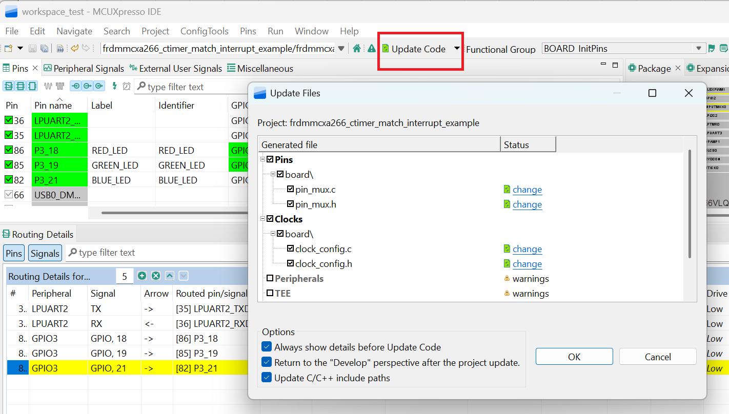
- 现在是时候导出由引脚工具生成的最新pin_mux.c和pin_mux.h文件,将这些更改实施到项目中。点击菜单栏中的“更新项目” 注:时钟和其他文件也可能被标记为正在更新,因为标题已被更改
- 我们在示例中添加一些额外的代码。打开simple_match_interrupt.c文件,并添加以下宏来初始化蓝色LED和绿色LED
- 添加一个宏,让LED代替CTIMER输出,这样我们就能更直观地观察板上的行为
- 按照上一节所述构建并下载项目
- 运行应用。您现在应该能看到绿色和蓝色LED来回切换
- 终止调试会话
5. MCUXpresso Developer Experience(MCUXpresso开发人员体验)
请查看以下各个章节,了解灵活的原型设计和开发生态合作体系。在下面的视频中,我们将向您介绍FRDM平台、功能齐全的EVK和兼容的扩展板。另外,我们还将带您浏览Application Code Hub (应用代码中心)页面,让您了解许多通过恩智浦Github提供的应用示例。
5.1 FRDM平台、功能齐全的EVK和扩展板
为了加速平台原型制作,我们提供了低成本FRDM平台和功能齐全的评估套件。
FRDM开发板具有标准规格和接头,便于连接MCU的输入/输出端口,并内置了MCU-Link调试器,带有USB-C线。我们的评估套件功能齐全,包括扩展的输入/输出和接口访问,支持通过WiFi和其他MCU-Link功能进行扩展。此外,还有许多兼容的Click板和/或Arduino扩展板。对于受开放Cortex微控制器软件接口标准(CMSIS)包支持的器件,示例项目可能已在ACH上提供。如未提供,许多器件仍可通过I²C、串行外设接口(SPI)和通用异步收发器(UART)等串行接口轻松使用——这些接口的驱动程序和示例代码包含在MCUXpresso软件开发工具套件(SDK)中。
5.2 Application Code Hub (应用代码中心)
Application Code Hub (应用代码中心)提供了一个交互式仪表板来快速定位软件,进一步增强了MCUXpresso Developer Experience。现在就访问ACH ,开始探索及发现新的交互式Application Code Hub(应用代码中心)的更多细节和优势。
ACH中的软件位于恩智浦GitHub存储库 ,因此可以直接从该位置轻松访问和克隆。
5.3 演示纵览
以下演示引导我们使用基于FRDM平台的系统从ACH导入一个项目,该系统具有电机控制扩展板和低成本LCD。尽管您的评估板可能与该系统有所不同,但以下步骤是通用的,适用于所有支持的平台。