SAF8544 Pluto传感器雷达参考设计快速入门
本文档内容
-
开箱即用
-
硬件介绍
-
操作Pluto传感器
1. 开箱即用
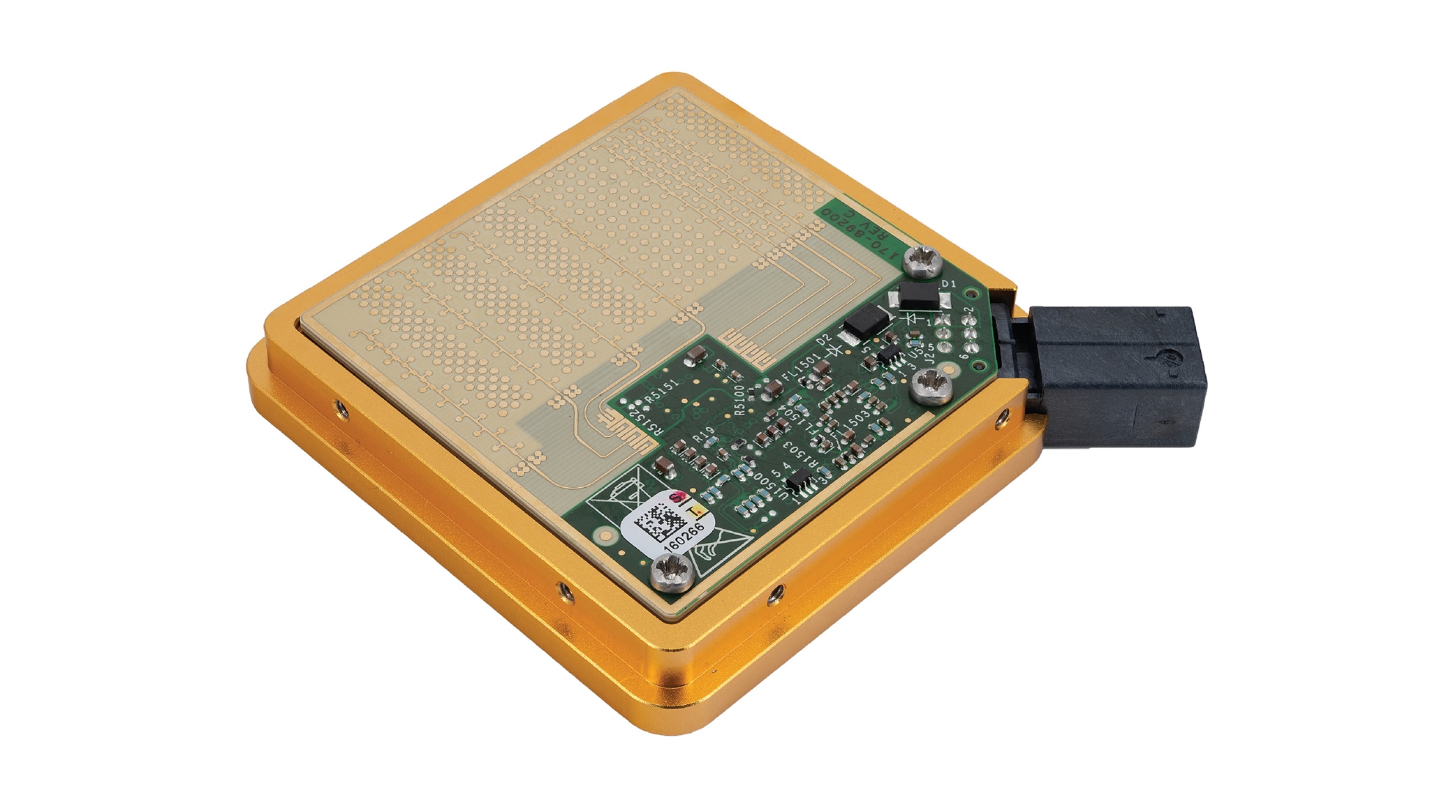
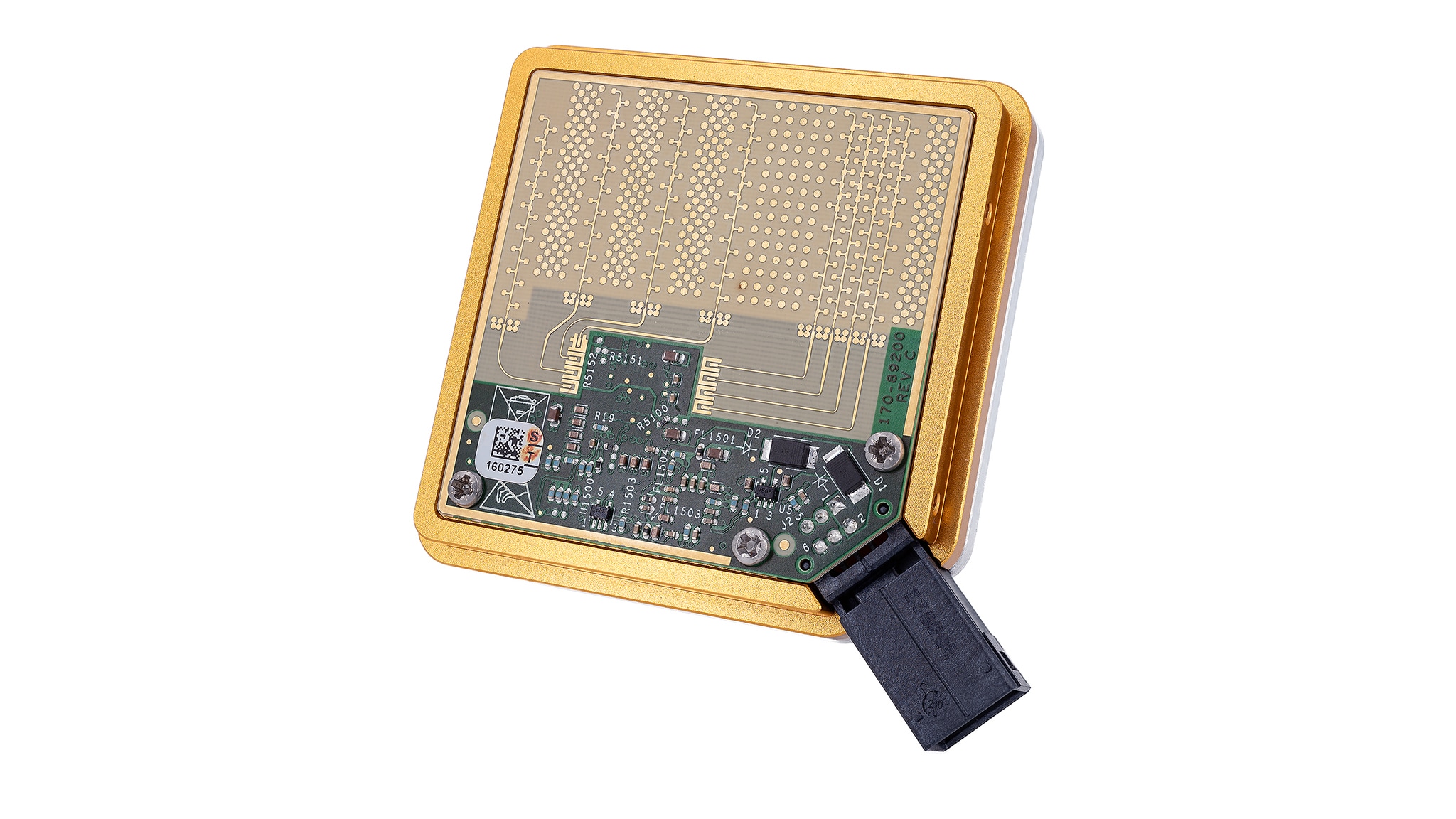
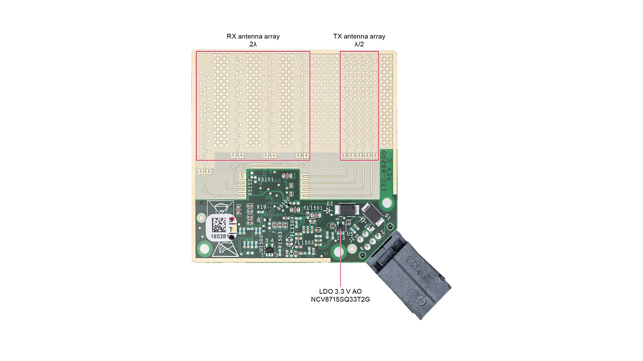
恩智浦Pluto传感器是一款基于RFCMOS片上系统(SoC) SAF8544的角雷达应用方案。该应用包含印刷天线参考平面。天线阵列由4个部分组成,每个部分在SoC两侧各包含10个天线贴片元件。其中一个天线平面专用于SoC发射天线平面,还有一个专用于接收天线平面。PCB上的发射(Tx)和接收(Rx)天线馈电结构经过布线设计,以确保电气通路长度相等。两个连续天线阵列结构之间的间距为2*λ (接收天线平面)和λ/2 (发射天线平面),且每个连续天线阵列之间均有接地图案。
1.1 套件内含物/装箱单
- 1个Pluto传感器
- 1根电源/汽车以太网线
该评估套件内含Pluto传感器及一根电源/汽车以太网线。此外,设置还需一个媒体转换器,以实现汽车以太网(1000BASE-T1)与标准以太网(1000BASE-T)之间的全双工1Gb通信,因为两者采用不同的物理层规格及线缆类型(单对双绞线vs.四对双绞线)。
1.2 ESD警告
注意
该器件容易受静电放电(ESD)影响。因此在运输和搬运过程中应小心谨慎。在打开包装或搬运硬件之前,请使用接地线或触碰电脑机箱或其他接地装置。
2. 硬件介绍
2.1 主要特性
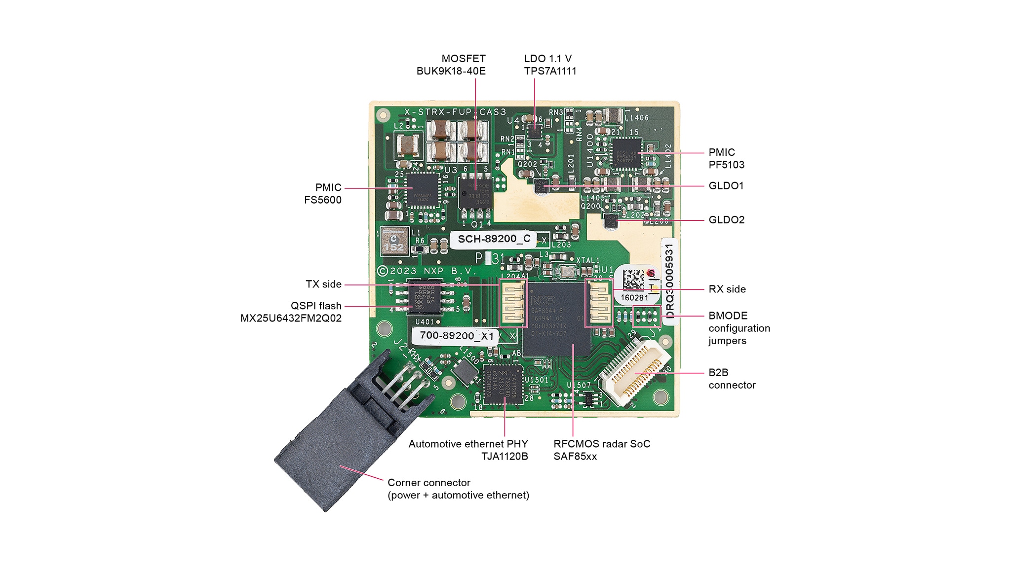
下图展示了Pluto板的主要特性。雷达传感器集成了SAF8544 28nm RFCMOS SoC、汽车以太网PHY TJA1120B、两个电源管理集成电路(PMIC) FS5600和PF5103、用于接收链路的全局低压差稳压器1(GLDO1)和用于发射链路的GLDO2、闪存、用于1.1V的低压差稳压器。边角连接器提供12V电源电压、汽车以太网接口及接地引脚。板对板连接器(B2B Connector)为数字域提供1.8V电源电压,为模拟域提供3.3V电源电压,并提供与JTAG、CSI和I²C总线接口的连接。
Pluto板的顶面包含接收和发射天线阵列。接收天线阵列由4个接收天线元件组成,间距为2λ;而4个发射天线的间距为λ/2。关于天线阵列及其特性的更多信息,请参阅UM11963 SAF8544参考设计用户手册——Pluto传感器。下图展示了Pluto板的天线侧。
2.2 结构框图
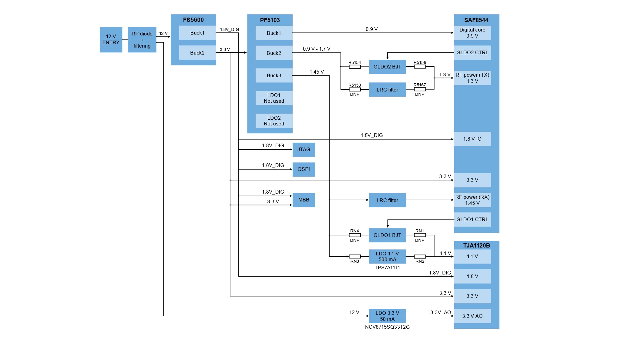
本节提供的框图展示了Pluto板的主电源连接。该雷达应用使用12V输入电压供电,该电压由一个RP二极管进行滤波。12V电源同时为生成常开3.3V电压的LDO和恩智浦PMIC FS5600供电。
FS5600的输出包括由Buck1生成的1.8V电压和由Buck2生成的3.3V电压。1.8V电压主要用于为输入输出(IO)数字域供电,而3.3V电压则用作恩智浦PMIC PF5103、恩智浦TJA1120B汽车以太网PHY、MBB接口以及为SAF8544供电的输入电压。
恩智浦PMIC PF5103包含3个内置Buck转换器,即Buck1、Buck2、Buck3,以及两个内置LDO (在当前应用中未使用)。Buck1输出生成稳定的0.9V电压,为SAF8544数字内核供电。Buck2能够生成0.9V-1.7V范围内的电压,通过GLDO2 BJT或LRC滤波器为SAF8544发射域供电。Buck3生成1.45V电压,通过LRC滤波器为SAF8544射频功率接收域供电。此外,Buck3通过GLDO1 BJT或LDO连接到TJA1120B,以生成稳定的1.1V电压。
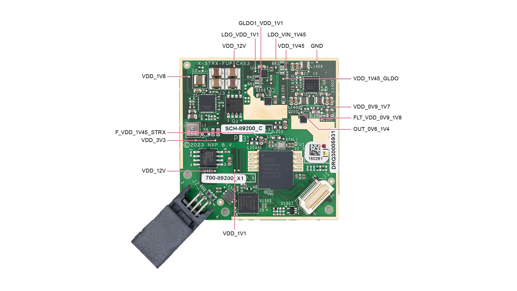
2.3 Pluto板测试点
提供了多个测试点,作为各项测量的参考点。电压测量需使用高精度数字万用表,该万用表连接到板上对应不同电压的可用测试点。本节图示中给出了板上测试点的说明。
注:必须强调的是,这些电压的测量应相对于公共参考接地,以保持正确的电势差。板上有多个参考接地点(参阅相关的Pluto板原理图)。
| 测试点 | 说明 |
|---|---|
| VDD_12V | 12V输入电压的测试点 |
| VDD_3V3 | 3V3模拟电压的测试点 |
| VDD_1V8 | 1V8数字电压的测试点 |
| VDD_0V9 | Buck1 0V9输出数字电压的测试点 |
| VDD_0V9_1V7 | Buck2 0V9–1V7输出电压的测试点 |
| VDD_1V45 | Buck3 1V45输出电压的测试点 |
| FLT_VDD_0V9_1V8 | LRC滤波器1V3输出电压的测试点(SAF85xx射频功率(RX) 1V45输入电压) |
| F_VDD_1V45_SAF85XX | SAF85xx射频功率(RX) 1V45输入电压的测试点 |
| OUT_0V6_1V4 | GLDO2 1V3输出电压的测试点(SAF85xx射频功率(TX) 1V3输入电压) |
| VDD_1V45_GLDO | GLDO1 1V45输入电压的测试点 |
| GLDO1_VDD_1V1 | GLDO1 1V1输出电压的测试点 |
| LDO_VIN_1V45 | LDO 1V45输入电压的测试点 |
| LDO_VDD_1V1 | LDO 1V1输出电压的测试点 |
| GND | 测试点接地 |
3. 操作Pluto传感器
3.1 连接传感器
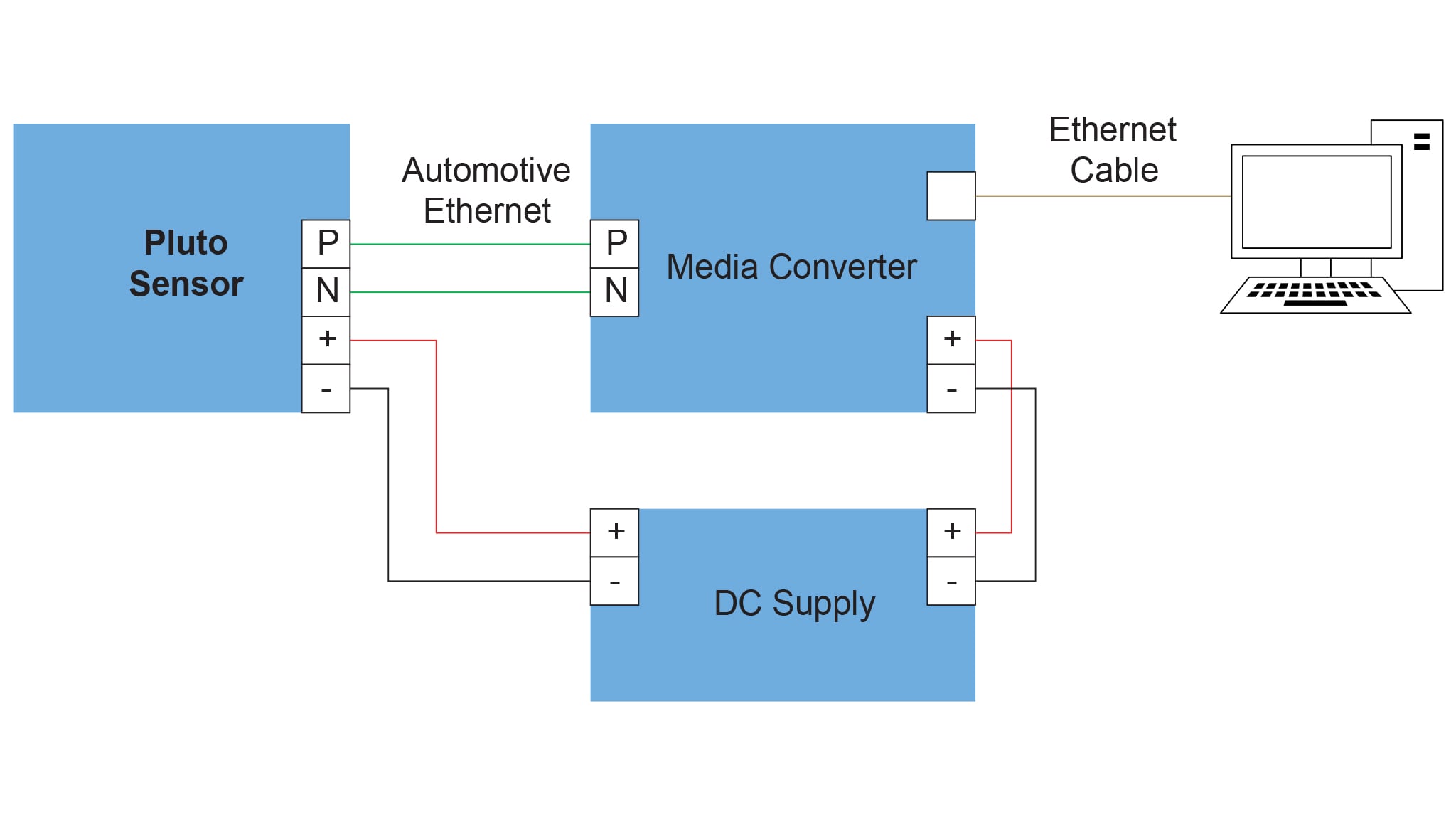
下图所示的框图展示了Pluto传感器通过媒体转换器与PC的连接方案。该媒体转换器将汽车以太网转换为标准以太网,并提供1000Mbit全双工通信。使用能够提供双路12V输出的DC电源,同时为Pluto传感器和媒体转换器供电。
3.2 操作网络引导加载程序
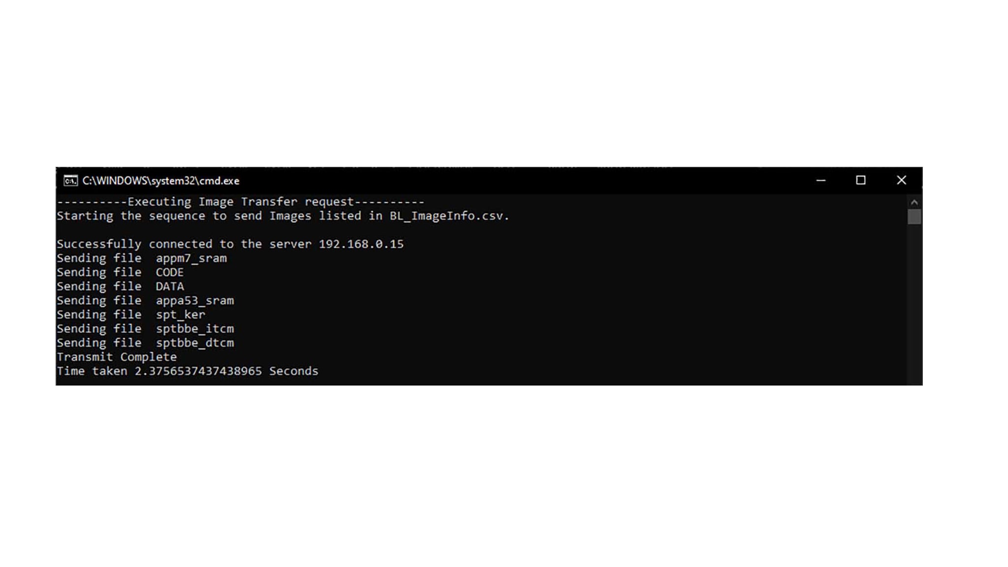
Pluto传感器内部已烧写了网络引导加载程序。如有需要,用户可以创建下载包。具体操作方法请参阅UM11889《网络引导加载程序用户手册》。为使用演示雷达固件,需先从nxp.com网站下载SAF85xx雷达集成软件包。该软件包内含预先生成的雷达演示固件包,可通过以太网加载至Pluto传感器内部:
- 启动雷达传感器,将汽车以太网线连接至媒体转换器,再用以太网线将媒体转换器连接至PC,如图XX所示
- 检查正在运行的PC的网络连接设置,即确保IP地址设置为“192.168.0.XX”,其中“XX”为除“01”或“15”之外的任意数字。注意,“192.168.0.15”和“192.168.0.01”地址分别被预留给Pluto设备和网关使用
- 转到已下载的SAF85xx雷达集成软件包内的网络引导加载程序包(文件夹)
- 运行此批处理文件(.bat)
雷达固件可与同样包含在SAF85xx雷达集成软件包中的Radar Xplorer配合使用。