Basic Connected Human Machine Interface (HMI) Solution
本文档内容
-
Basic Connected HMI Solution Hardware
-
Application Overview
-
Setup
-
Put the Boards Together
-
Basic Connected HMI Software
-
Run the Demo

1. Basic Connected HMI Solution Hardware
This section explains the required hardware and miscellaneous hardware and tools needed for Basic Connected Human Machine Interface (HMI).
1.1 Required Hardware
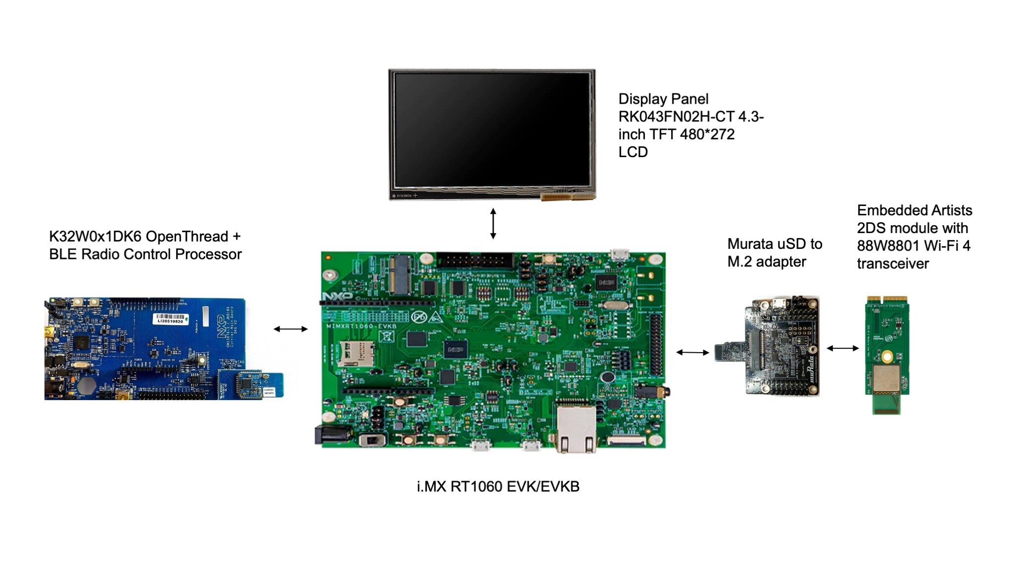
The hardware required to assemble, wire, and run the Basic Connected Human Machine Interface (HMI) application is listed below:
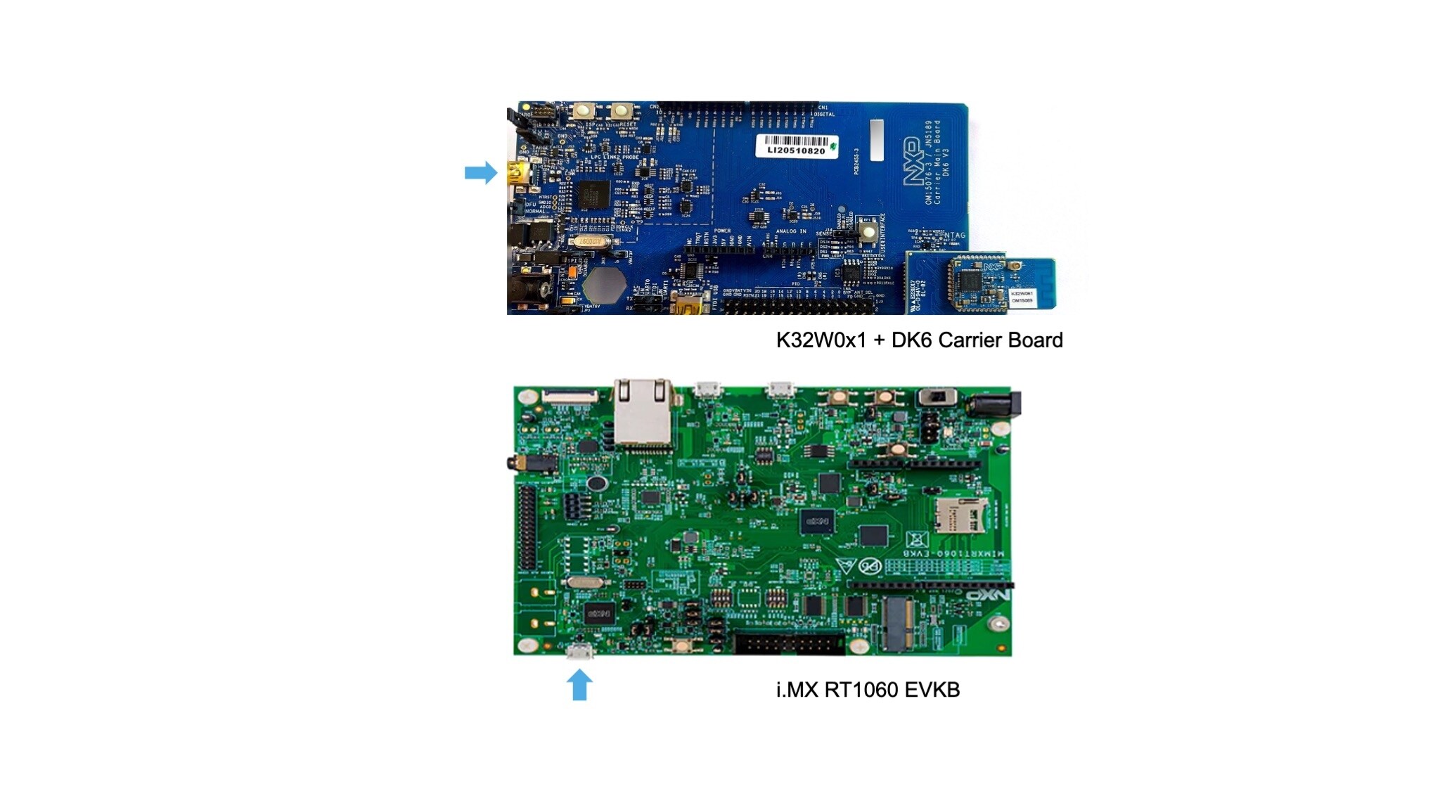
- i.MX RT1060 EVK/EVKB
- RK043FN02H-CT 4.3-inch TFT 480*272 LCD
- Embedded Artist 2DS M.2 Wi-Fi module (based on 88W8801)
- Murata uSD to M.2 adapter
-
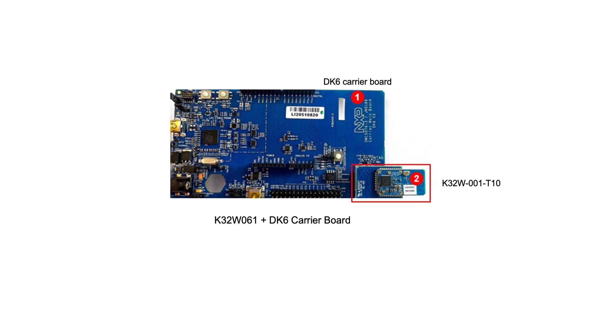
DK6 carrier board from the Advanced Development Kit for
K32W061andJN5189/88(IOTZTB-DK006) -
K32W-001-T10 module with
K32W061from the Advanced Development Kit forK32W061andJN5189/88(IOTZTB-DK006)
1.2 Various Hardware and Tools
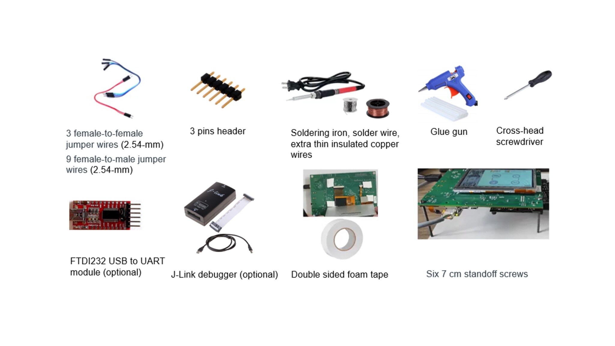
The various hardware and tools required to assembly the platform are shown below:
- 2.54-mm jumper cables: 20 cm 3 female-to-female for PTA lines, 20 cm 10 female-to-male for UART and OTW connections between DK6 and i.MX RT1060 EVK/EVKB
- Soldering iron, solder wire, glue gun, extra thin insulated copper wires, 3 pins header (for reworking the Embedded Artist 2DS M.2 Wi-Fi module)
- Cross-head screwdriver
- J-Link debugger (optional)
- FTDI232 USB to UART module (optional)
- Double sided foam tape
- Six 7 cm standoff screws
2. Application Overview

3. Setup
This section details the necessary hardware preparations, before assembling the setup.
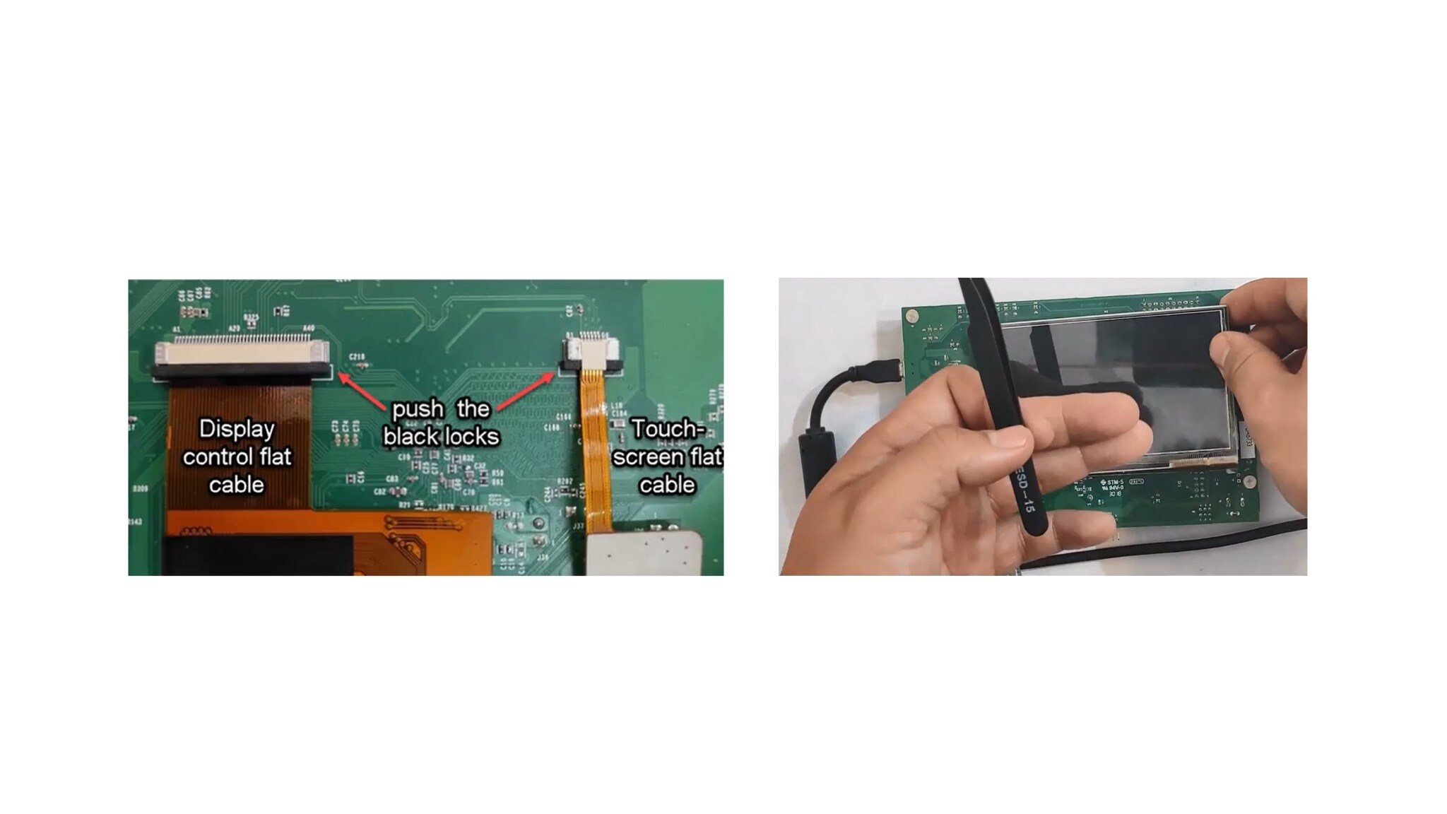
3.1 Mount the Display Panel on the i.MX RT1060 EVK
On the i.MX RT1060 EVKB, the LCD panels can be connected at J49 (A1-A40) and Capacitive Touch Panels (CPT) can be connected at J49 (B1-B6).
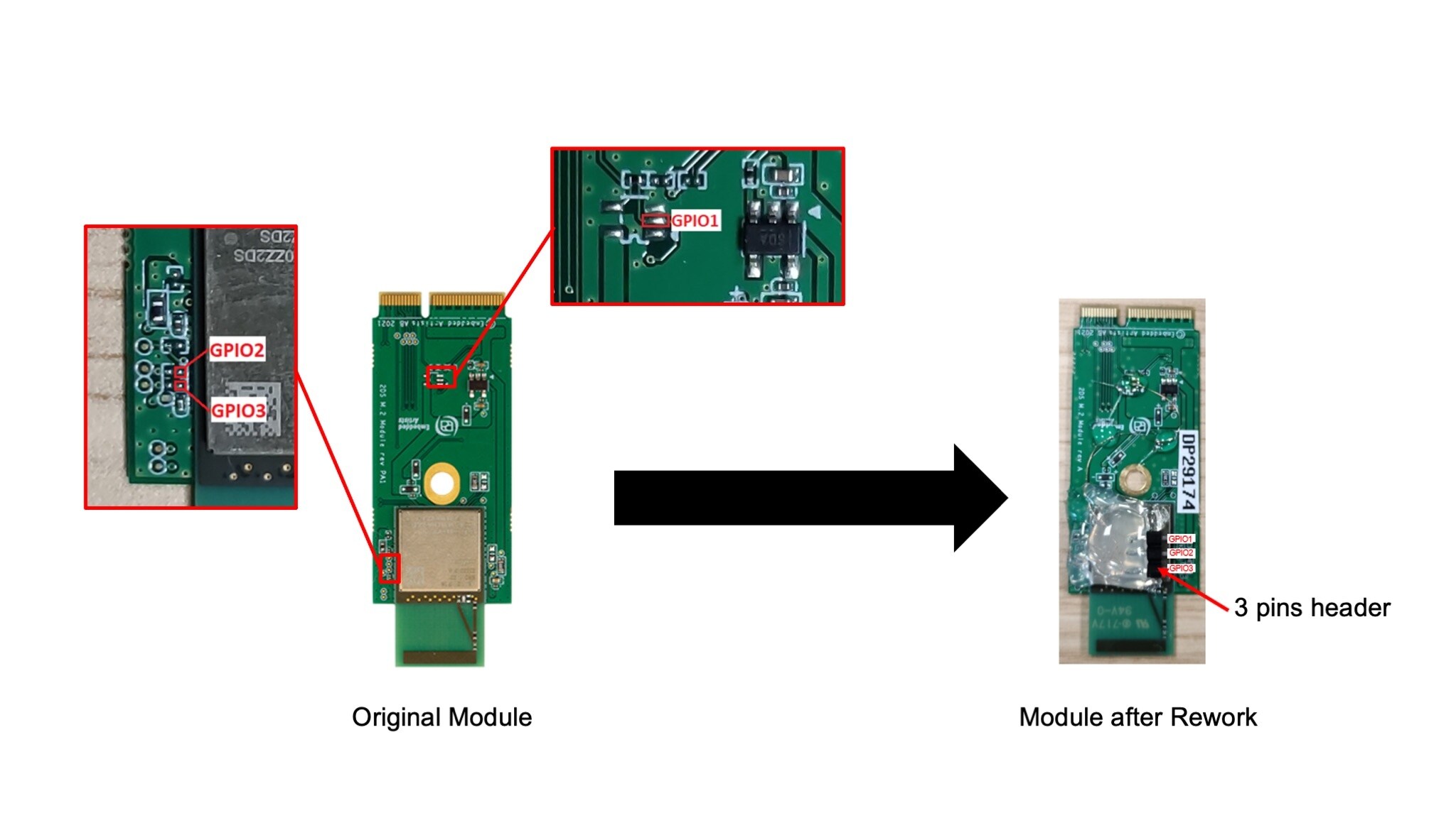
3.2 Rework the Embedded Artist 2DS M.2 Module (to Enable Coexistence)
- To enable coexistence, you need to rework the Embedded Artist 2DS M.2 Wi-Fi module, so that the PTA (Packet Traffic Arbitration) lines are exposed
- GPIO1 – GRANT
- GPIO2 – PRIO
- GPIO3 – REQ
- Locate GPIO1, GPIO2 and GPIO3 on the board, as shown in the attached pictures
- Use the thin insulated copper wires to connect the pads to the 3 pins header
- Use a glue gun to glue the pin header to the board
The picture below shows the pads that correspond to the GPIOs required by PTA:
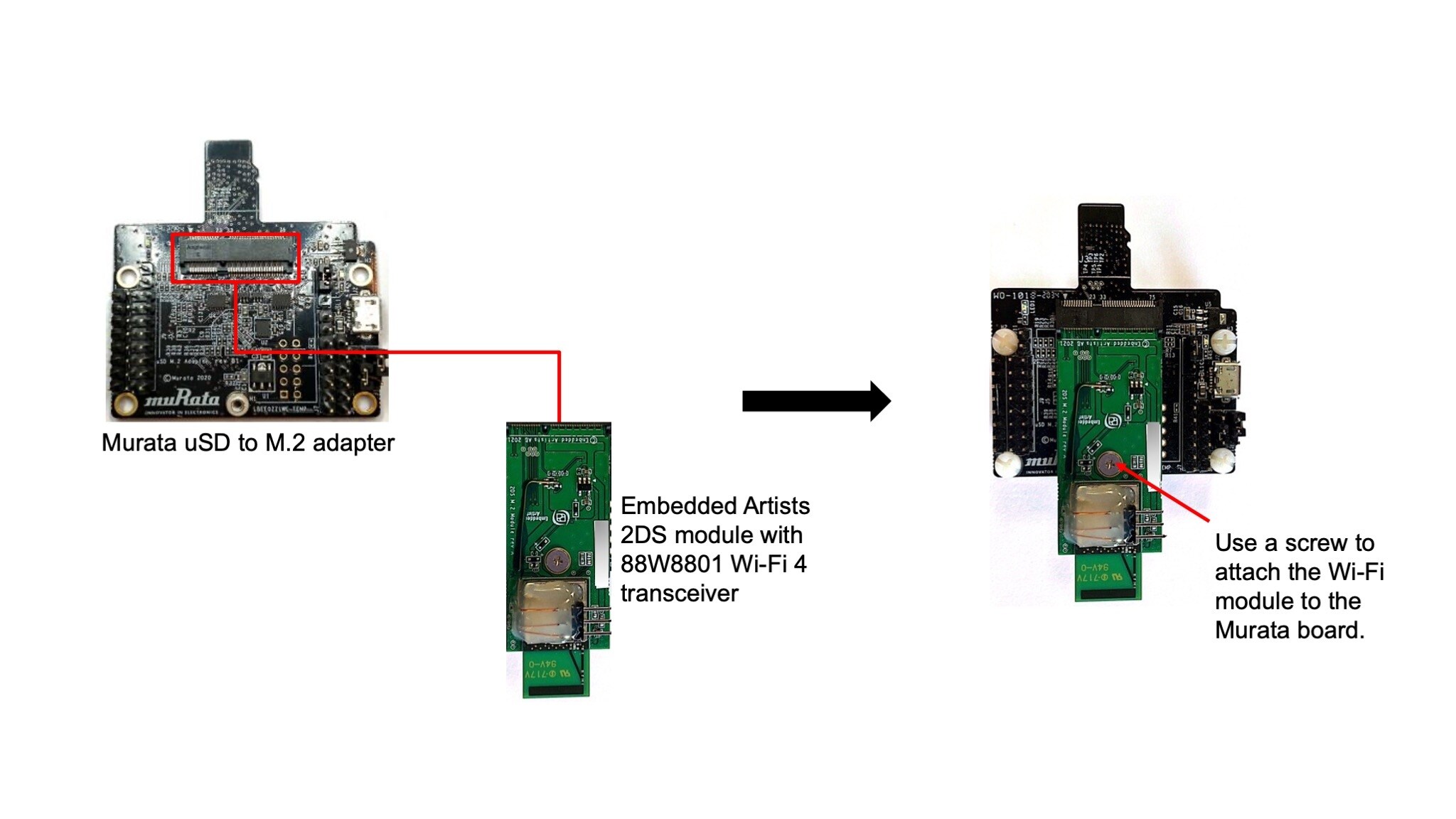
3.3 Connect the Wi-Fi module to the USD to M2A Adapter
Connect the Embedded Artists 2DS Wi-Fi module to the Murata uSD to M2 adapter. We will call this assembly Wi-Fi board.
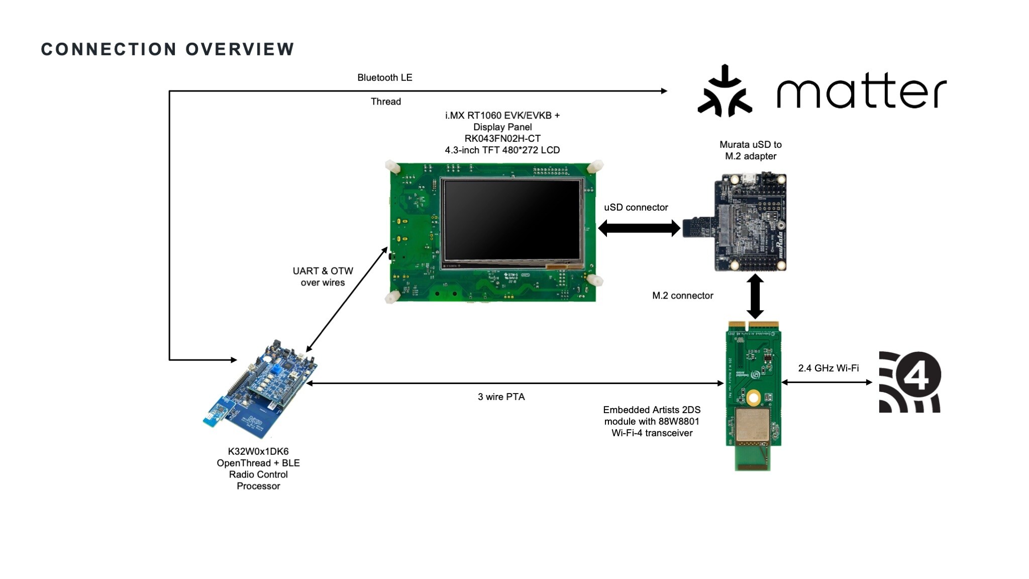
4. Put the Boards Together
The attached picture shows an overview of the connections involved in the Basic Connected HMI solution. The 3 wires PTA is mandatory when coexistence is enabled.
Assembly
Connecting all the boards of the platform is explained in the steps below.
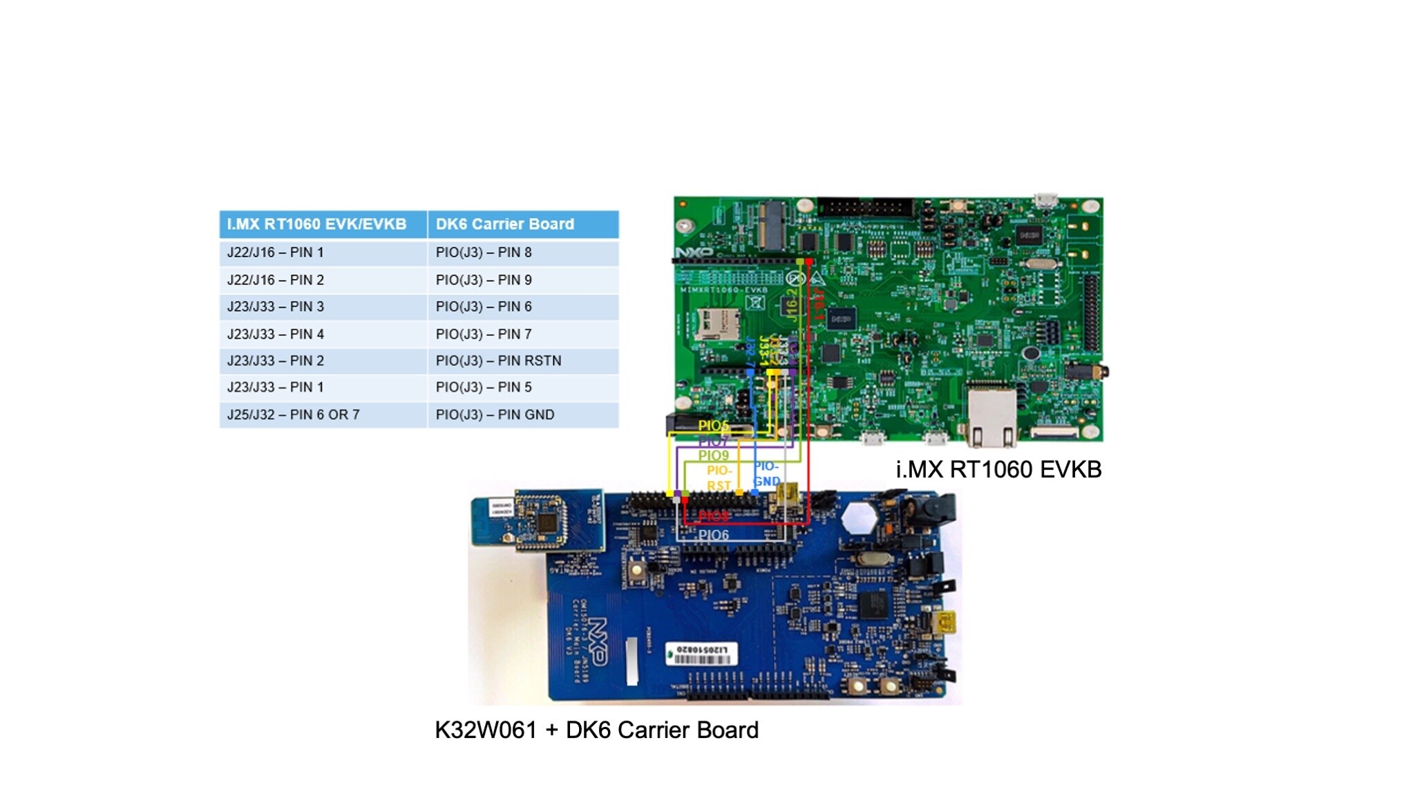
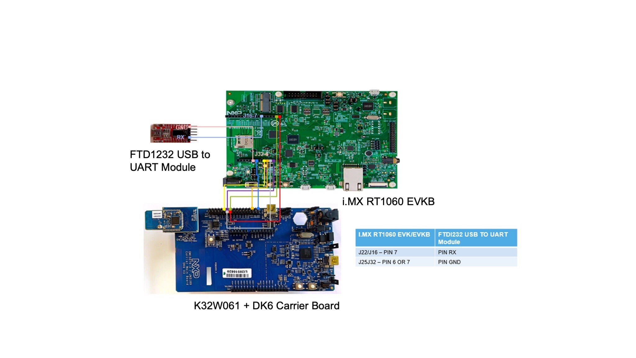
4.1 Connect the i.MX RT1060 EVK/EVKB to the DK6 Carrier Board
Using 7 female to male jumper wires make the connections as described in the picture.
Connect the FTDI232 Module (Optional, for Matter Logs)
This step is optional, and creates a separate debug console for printing logs separated that in Matter CLI console. Prebuilt binaries are printing debug logs on the same interface as the Matter CLI, so an extra debug console is not required in that case. However, if you choose to separate the debug console from the Mater CLI, you need to add an FTDI232 USB to UART module and build the application accordingly.
The FTDI232 USB to UART module can be integrated in the setup using 2 female to male jumper wires to make the connections as described in the picture.
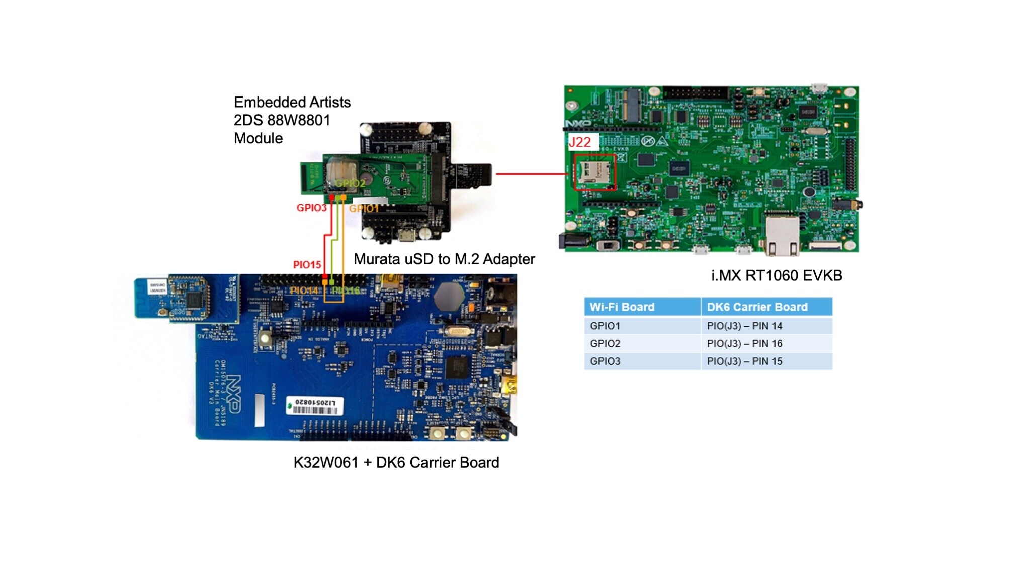
4.2 Integrate the Wi-Fi Module
- Connect the Wi-Fi board to
J39/J22of the i.MX RT1060 EVK/EVKB - To enable coexistence, add the PTA lines between the Wi-Fi board and the DK6 carrier board, as shown in the picture, using 3 female to female jumper wires
4.3 Configure the Board for Debugging
To debug the i.MX RT1060 EVK/EVKB, you can opt for the on-board debugger or for an external debug probe. Steps A and B show how to configure the board for these scenarios.
Choose either step A or B.
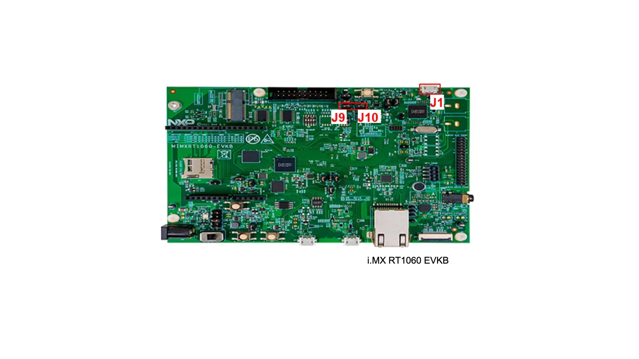
A: Debug Using the On-board Debugger
For flashing the boards and possible debug activities, configure the i.MX RT1060 EVK/EVKB board as following:
- Close
J47/J9andJ48/J10 - Connect the USB cable from the i.MX RT1060 EVK/EVKB kit to
J41/J1
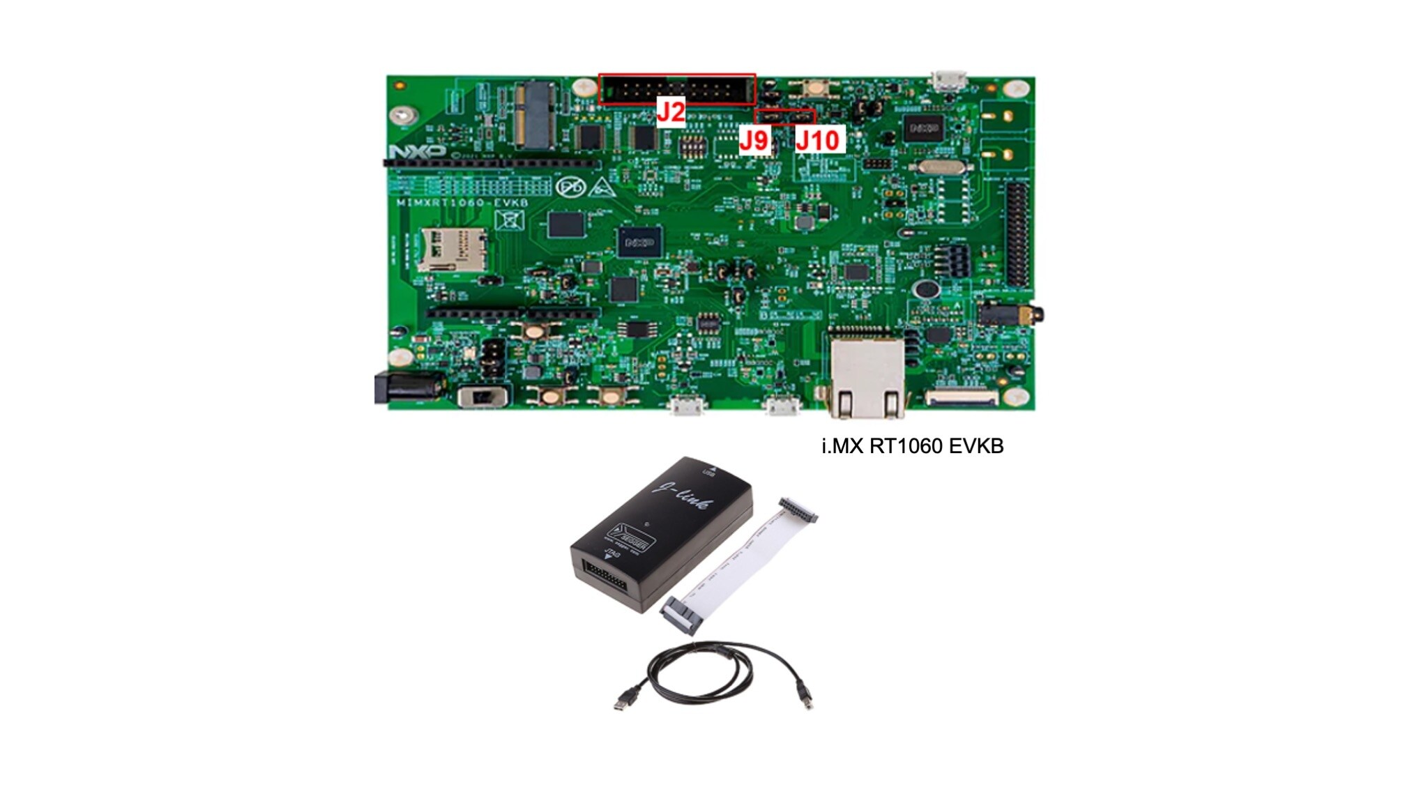
B (Optionally): connect the external debugger
If you prefer to use the J-Link external debugger, configure the the i.MX RT1060 EVK/EVKB board as following:
- Open
J47/J9andJ48/J10 - Connect the J-Link debug probe to
J21/J2
4.4 Power Connection
The DK6 carrier board can be powered through a USB cable or by adding a male to female jumper wire between the i.MX RT1060 EVK/EVKB and the DK6 carrier board.
Now, the system can be powered through a USB cable connected to the J41/J1 i.MX RT1060 EVK/EVKB.
5. Basic Connected HMI Software
In this section we show how to get the Basic Connected HMI software package and flash the board using MCUXpresso IDE.
5.1 Prepare MCUXpresso IDE Environment
In this step we prepare the MCUXpresso IDE environment, needed to flash the board with the integrated debugger.
- Download and install MCUXpresso
- Build and download the MCUXpresso SDK for i.MX RT1060 EVK/EVKB available here: MCU Xpresso SDK Builder
- Open the MCUXpresso IDE
-
From the File Explorer window, drag and drop the i.MX RT1060 EVK/EVKB SDK archive into the MCUXpresso IDE Installed SDKs
window. When the installation completes, the SDK will appear as
SDK_2.x_MIMXRT1060-EVK/EVKB -
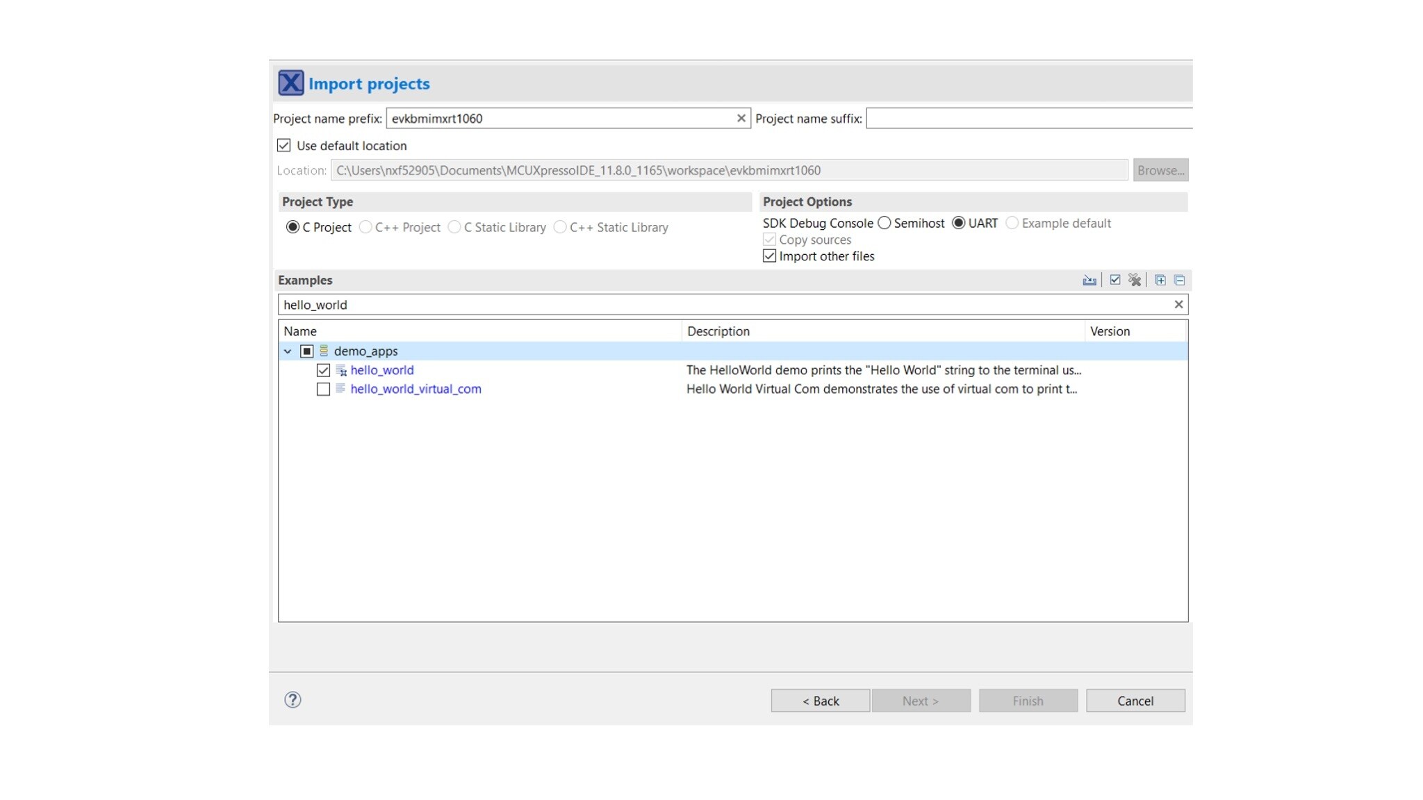
Import an example from the previously installed SDK:
QuickStart Panel > Create or import a project > Import SDK example(s) > Select evkbmimxrt1060 > Import hello_world example - Connect the Basic Connected HMI hardware via the USB cable to your computer
- Select the imported hello_world project and click the Debug button. A probes discovered pop-up will appear. Select your CMSIS-DAP instance and press OK. Note that after this step, MCUXpresso IDE will start building and flashing the hello_world project
5.2 Get the Basic Connected HMI Software
Solution software is available here: https://github.com/nxp-appcodehub/ap-basic-matter-ready-connected-hmi.git
Download the software package as a zip or clone the Connectivity Toolbox repository containing the Basic Connected HMI application:
Ubuntu terminal:
user@ubuntu: ~/ git clone https://github.com/nxp-appcodehub/ap-basic-matter-ready-connected-hmi.git
5.3 Running the Demo Using Provided Binaries (1/2)
In the downloaded repository, go to the binaries/bchmi_RT1060_apps/ folder that contains pre-built binaries for the following configurations:
| Binaries | Hardware | Functionality | Use Case |
|---|---|---|---|
BCHMI_OTW_BLE_OT_DK6_MCLI_DISP.hex |
i.MX RT1060 and K32W0x1 RCP |
Matter over Open Thread | Standalone Matter Open Thread Node (Bluetooth LE for commissioning). Open Thread FTD device: ot-cli for network configuration |
BCHMI_Wi-Fi_NOcred_MCLI_DISP.hex |
i.MX RT1060 and 88W8801 |
Matter over Wi-Fi |
Standalone Matter Wi-Fi End Node |
BCHMI_OTW_OTAP_BLE_OT_DK6_Wi-Fi_NOcred_PTA_MCLI_DISP.hex |
i.MX RT1060, K32W0x1 RCP, and 88W8801 |
Matter over Open Thread Wi-Fi for non-Matter use case |
Standalone Matter Open Thread Node (Bluetooth LE for commissioning) Open Thread FTD device: ot-cli for network configuration Wi-Fi Connection /non-Matter use case Thread – Wi-Fi Co-existence/PTA |
5.4 Running the Demo Using Provided Binaries (2/2)
Notes:
- Provided binaries have Matter CLI and Display enabled. The Matter CLI and the debug console are combined in the same console
- Wi-Fi builds do not have credentials added at build time, so user can use the Matter CLI to input the required Wi-Fi commands to connect to the Wi-Fi network
-
Using Matter CLI means that Matter log output is moved to
LPUART2_TX on GPIO_AD_B1_02 pin. This requires using an external FTDI adapter with baudrate set to 115200 bauds
Next steps will describe how to flash the BCHMI_OTW_OTAP_BLE_OT_DK6_Wi-Fi_NOcred_PTA_MCLI_DISP.hex binary.
5.5 Flashing the Board Using MCUXpresso IDE
Perform the following steps in the MCUXpresso IDE:
- Import the Basic Connected HMI project in MCUXpresso IDE:
- After the steps in section 5.1 a .launch file is generated as part of the hello_project. We call this file a debug configuration
- Open the hello_world debug configuration file and edit it:
- Check the Disable auto build option
- Click Apply and Continue
- Flash the board using the updated debug configuration, by clicking the Debug button. Note that the hello_world project must be selected for this step
File > Import > C\C++ > Existing Code as Makefile ProjectMain > C\C++ Application > add the path to the BCHMI_OTW_OTAP_BLE_OT_DK6_Wi-Fi_NOcred_PTA_MCLI_DISP.hex binary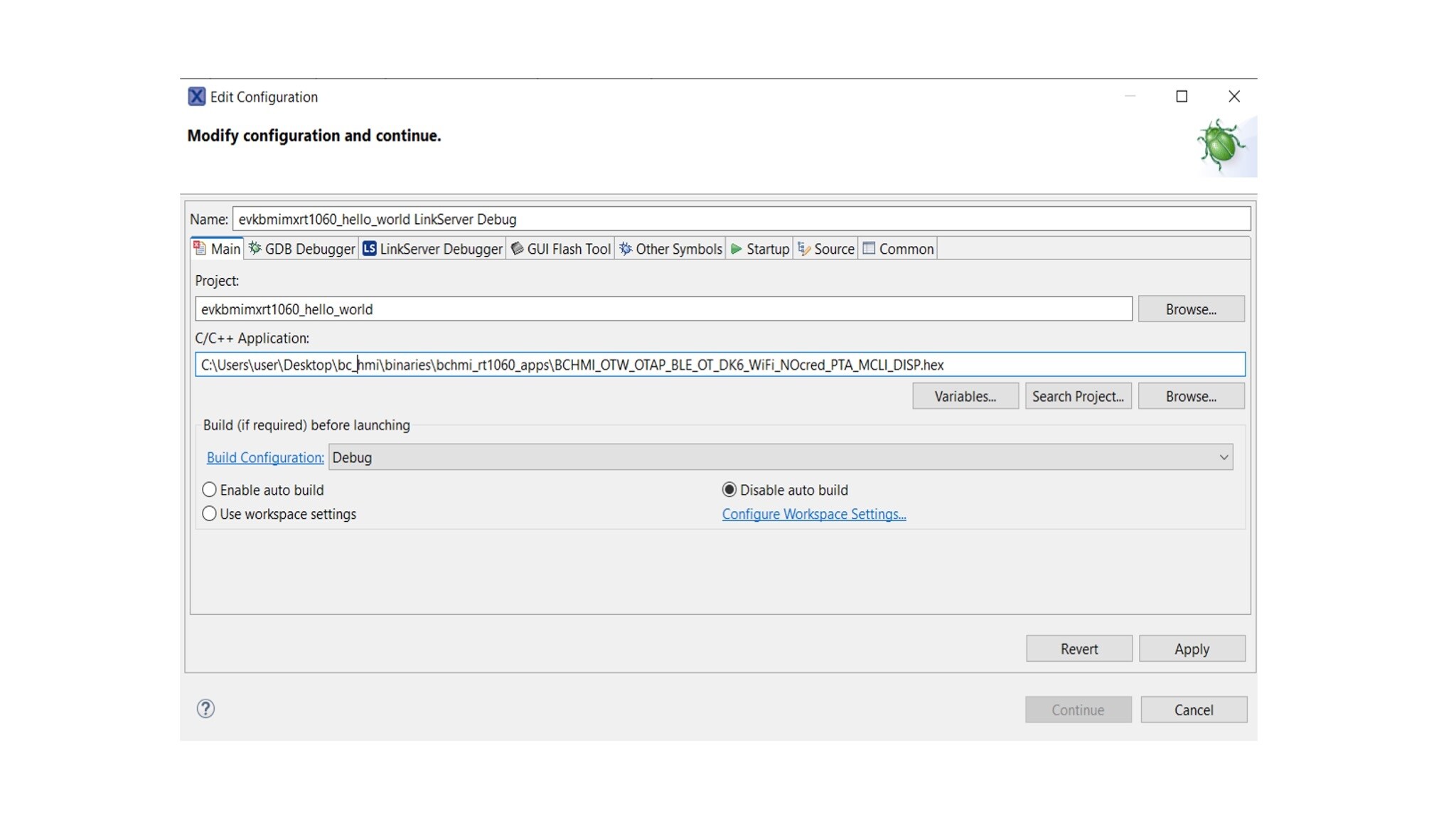
6. Run the Demo
This section describes how to join the Basic Connected HMI to a Matter network, how to exercise peer device control and how to connect to a non-Matter Wi-Fi network.
For running this demo, in addition to the Basic Connected HMI, you will need:
- A Matter controller and OpenThread Border Router (OTBR) using the i.MX8M Mini Processor family (Advanced Matter Development Platforms); The steps for this setup can be found in “Getting Started with i.MX 8M Mini and Matter”.
-
Generic switch Node (from the Advanced Development Kit for
K32W061andJN5189/88-IOTZTB-DK006) running a Matter Light device example. (The steps for this setup can be found in “Getting started with K32W0X1 in Matter”.) - A Windows or Linux Machine with at least 3 USB ports
- Wi-Fi Access point
- PuTTY - SSH connection / Terra Term – Serial Terminal
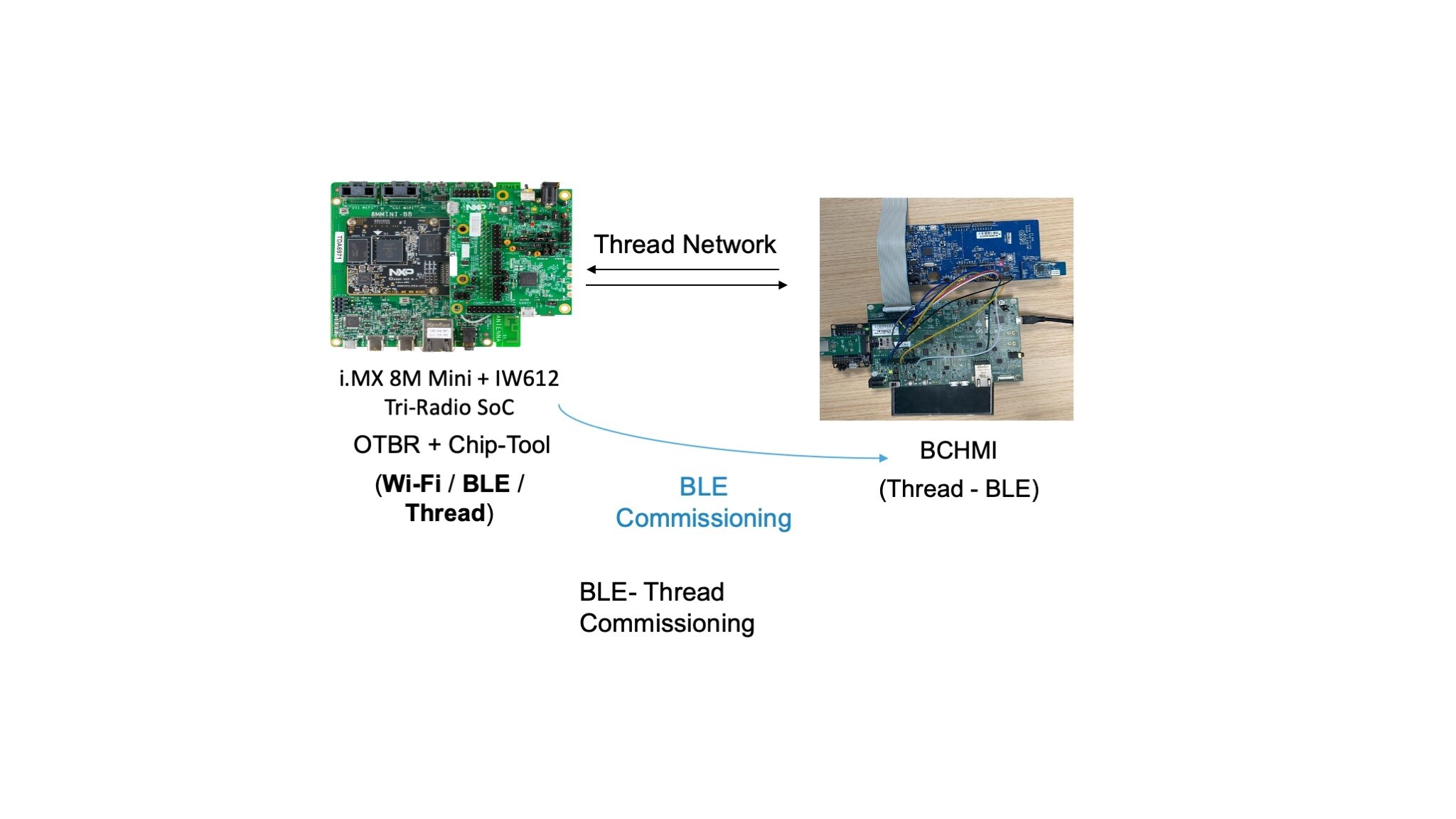
6.1 Joining the Basic Connected HMI to a Matter Network
Joining the Basic Connected HMI to a Matter network is done using BLE-Thread commisioning. The i.MX 8M Mini + IW612 Tri-Radio SoC will act as a Matter Controller. Further in this document we will refer to the i.MX 8M Mini + IW612 Tri-Radio SoC as Matter Controller board.
Setting Up the Matter Controller Board
- A Power on the Matter Controller board and connect it via USB to your Windows or Linux machine
- Use PuTTY to open a serial connection with the Matter Controller board (Controller CLI), with the following parameters:
- Baud rate: 115200
- 8 data bits
- 1 stop bit
- No parity
- No flow control
- After the boot sequence when you are prompted to type in an username use “root” (no password required)
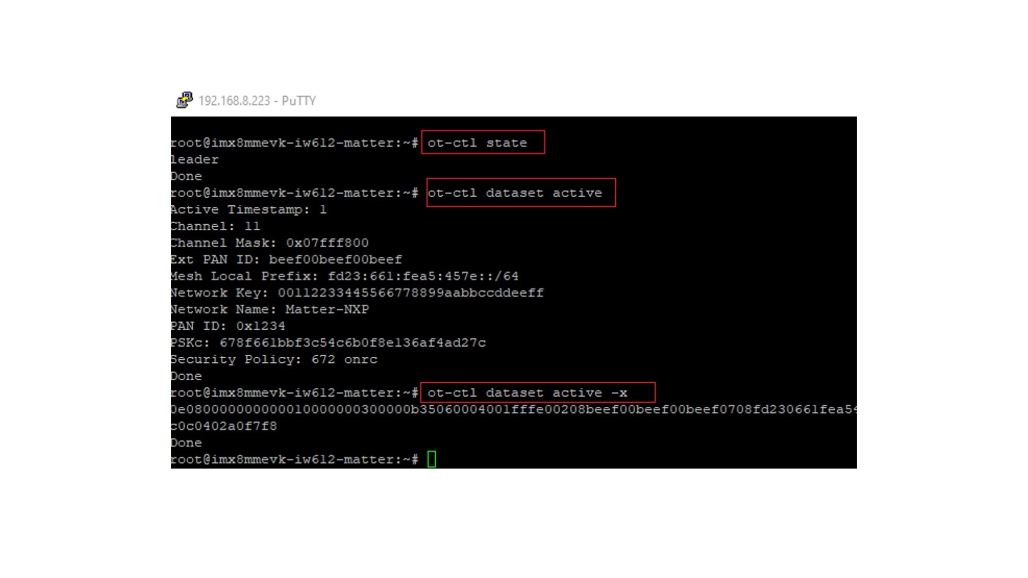
- The Matter controller board is acting as an OTBR (Open Thread Border Router). To check that this functionality has started after reset, use the following commands (the output should be similar to the one in the attached picture):
ot-ctl state
ot-ctl dataset active
ot-ctl dataset active -x
Start BLE Advertising on the Basic Connected HMI
- Using PuTTY, open a serial connection with Basic Connected HMI (Matter CLI) with the following parameters:
- Baud rate: 115200
- 8 data bits
- 1 stop bit
- No parity
- No flow control
- Factory reset BCHMI using the following Matter CLI command:
> matterfactoryresetThe BCHMI will enter the Bluetooth LE Advertising mode waiting for a commissioner to initiate the pairing procedure (Advertising Device name = Matter 3840).
Add the Basic Connected HMI to the Matter Network (1/2)
Using the Controller CLI, run the following commands on the Matter Controller board:
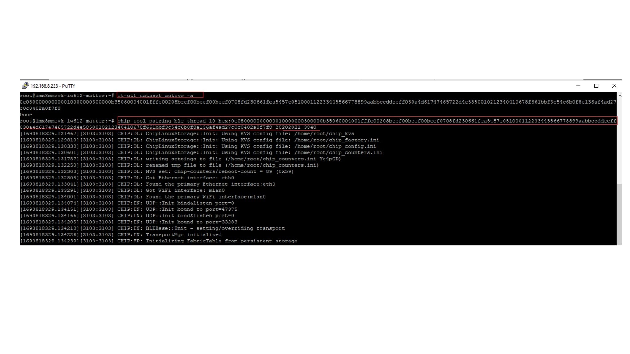
- Get the Thread network operational dataset:
- Issue a Matter pairing command to start the commissioning process (node_id = choose desired value, operational_dataset = from the previous step, pin_code = default value is 20202021, discriminator = default value is 3840)
ot-ctl state
ot-ctl dataset active
ot-ctl dataset active -x
$ chip-tool pairing ble-thread <node_id> hex:<operational_dataset> <pin_code> <discriminator>
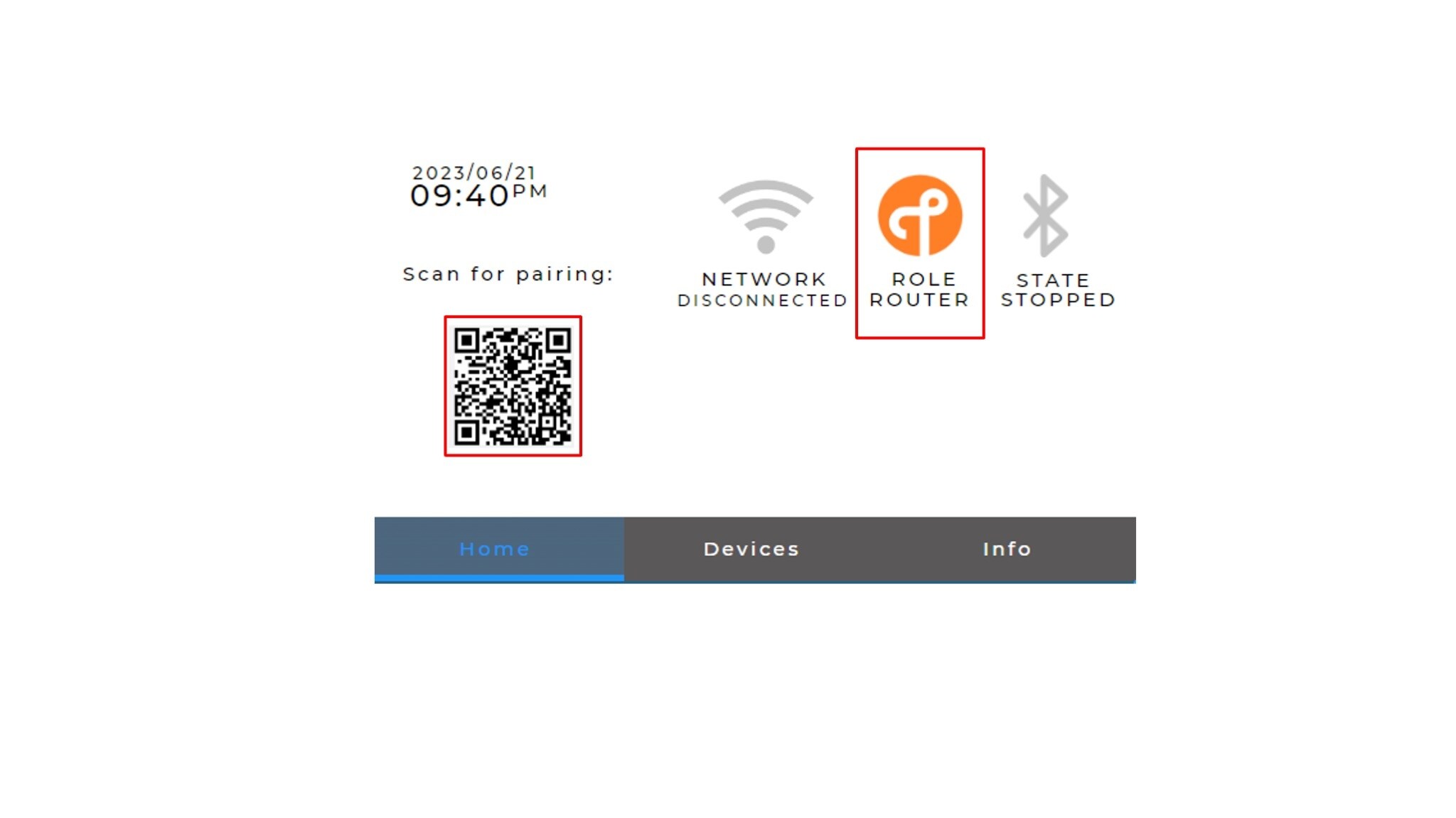
Add the Basic Connected HMI to the Matter Network (2/2)
Once the Matter commissioning process is completed with success, the Thread Status on the Basic Connected HMI will update with the corresponding role (e.g Router). The updated status can be seen on the display of the Basic Connected HMI.
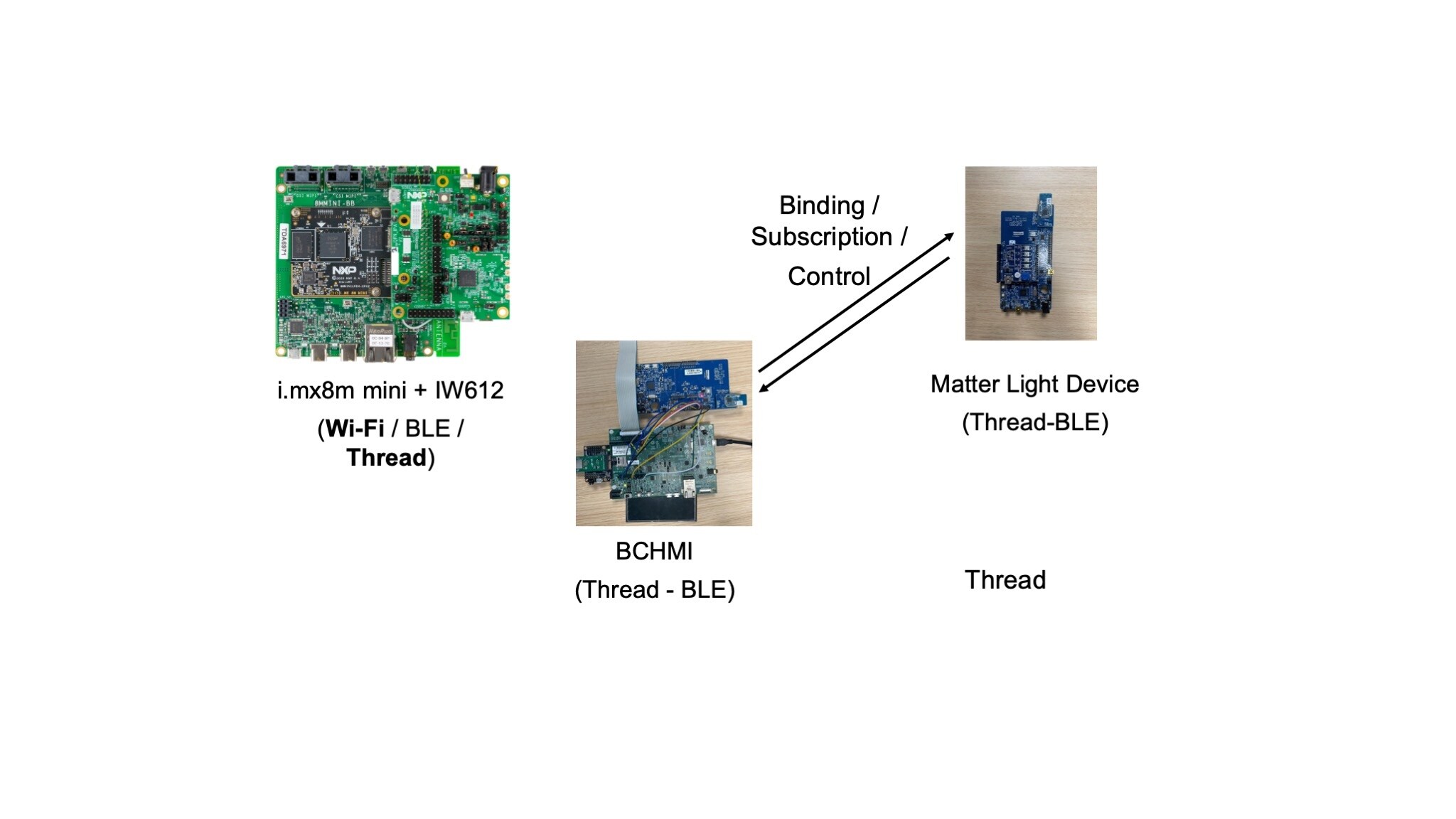
6.2 Peer Device Control
In this part, we will add the Generic switch Node (running Matter Light device example) into the Matter network and then use the BCHMI Display with touch screen to control the On/Off State of the Light device. Further in this document we will refer to the Generic switch Node as Matter Light device.
- From the Matter Controller, using the Controller CLI, add the Matter Light device into the network – same procedure as the one explained in section 6.1
- Bind the Basic Connected HMI with the Matter Light device in the network, by running the following commands on the Matter Controller board:
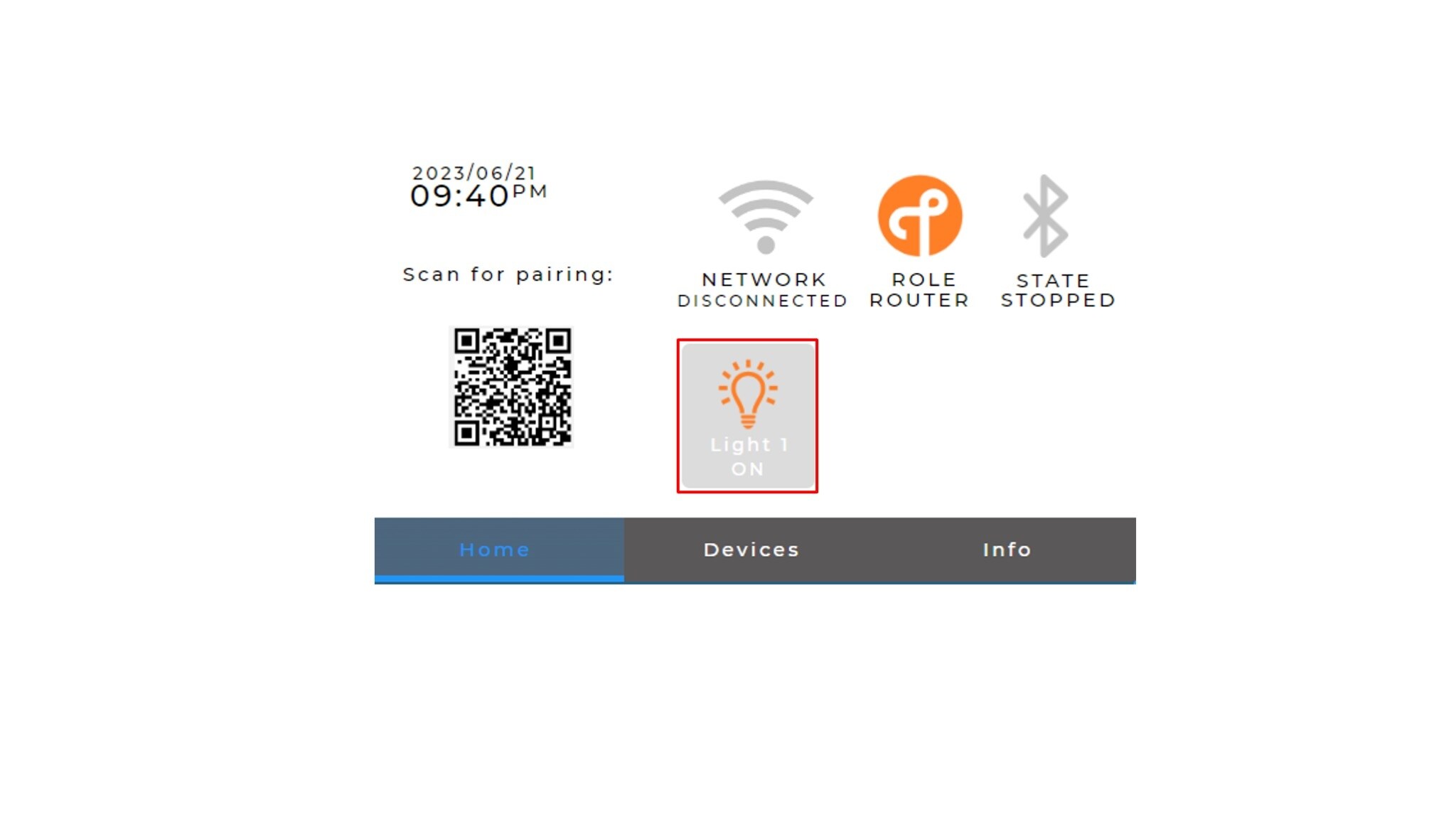
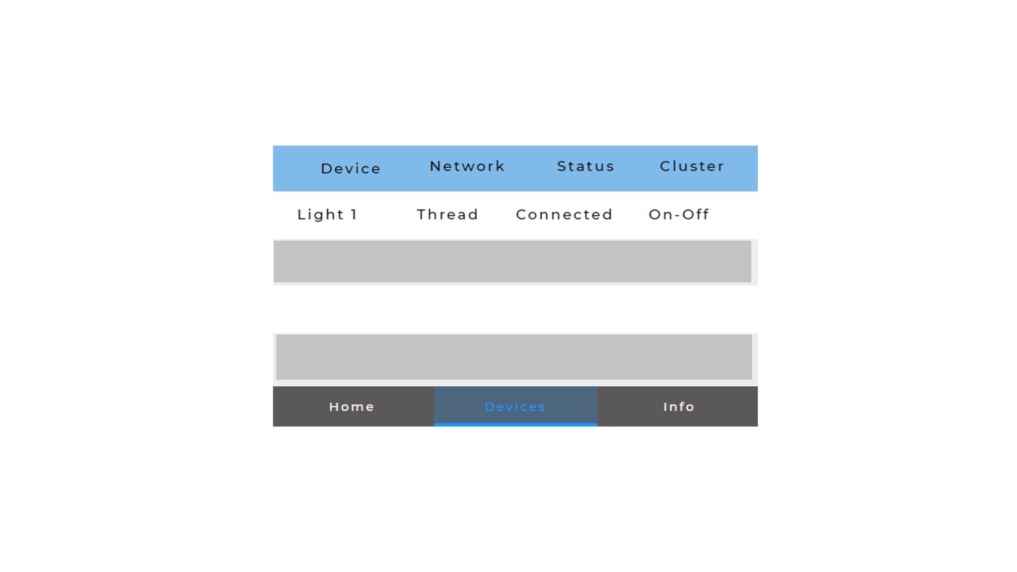
- On the Basic Connected HMI Display, the Matter Light device node will be listed on the Home Page and on the Devices Page as shown in the attached pictures:
- You can now control the device by pressing on the corresponding Light Icon from the Basic Connected HMI display. The subscription is automatically done at the first Light Icon press.
- Once the binding is performed, the subscription is also automatically done → if a peer device changes the state of the light, the BCHMI light state will be automatically updated.
$ ./chip-tool accesscontrol write acl '[{"fabricIndex": 1, "privilege": 5, "authMode": 2, "subjects": [112233], "targets": null },{"fabricIndex": 2, "privilege": 3, "authMode": 2, "subjects": [], "targets": null }]' 0
$ ./chip-tool binding write binding '[{"node" : , "cluster" : "0x0006" , "endpoint" : }]' 1
6.3 Connect to a Wi-Fi Network (NON-MATTER) (1/2)
Using the Matter CLI (opened in section Start BLE Advertising on the Basic Connected HMI) run the following steps:
- Scan for available Wi-Fi networks. Run the wifiscan command in the Matter CLI. This step is optional
- Choose the network you want to connect to
- Provide network credentials using the wifiadd command in the Matter CLI:
- Connect to the Wi-Fi network added in the previous step. Use the wificonnect command in the Matter CLI
> wifiscan> wifiadd wifiadd <ssid> <password>> wificonnect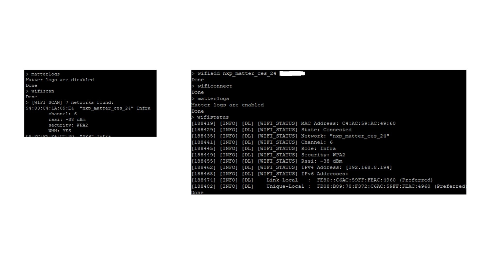
6.4 Connect to a Wi-Fi Network (2/2)
Check the status of the connection and get information such as the IPv4 and IPv6 addresses. Run the wifistatus command in the Matter CLI. The state connected/not connected is visible also on the Basic Connected HMI Display:
> wifistatus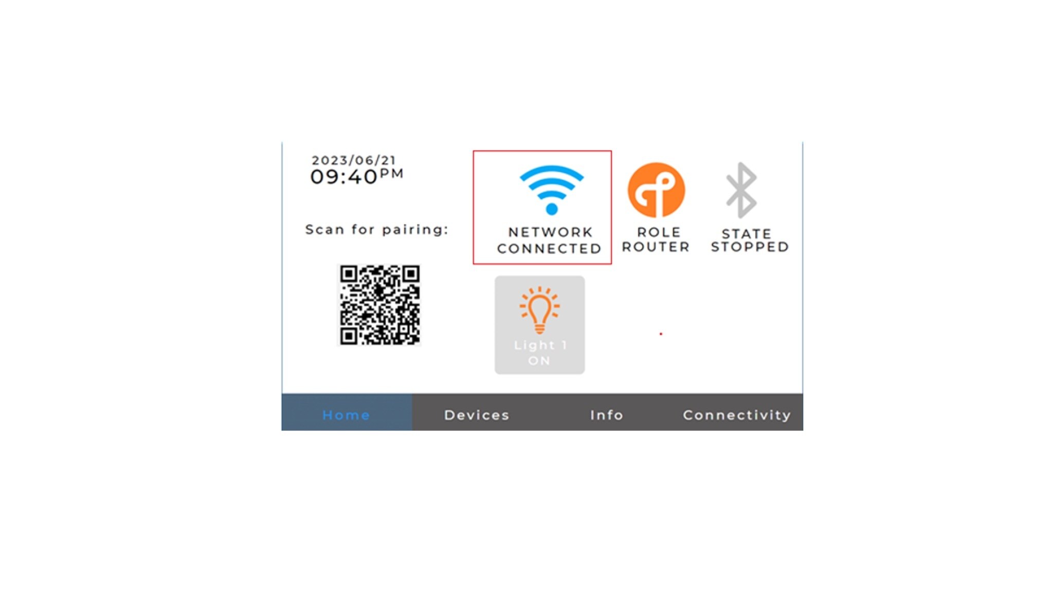
本页内容
- 3.1
Mount the Display Panel on the i.MX RT1060 EVK
- 3.2
Rework the Embedded Artist 2DS M.2 Module (to Enable Coexistence)
- 3.3
Connect the Wi-Fi module to the USD to M2A Adapter
- 3.4
Connect K32W-001-T10 Module to the DK6 Carrier Board
- 4.1
Connect the i.MX RT1060 EVK/EVKB to the DK6 Carrier Board
- 4.2
Integrate the Wi-Fi Module
- 4.3
Configure the Board for Debugging
- 4.4
Power Connection