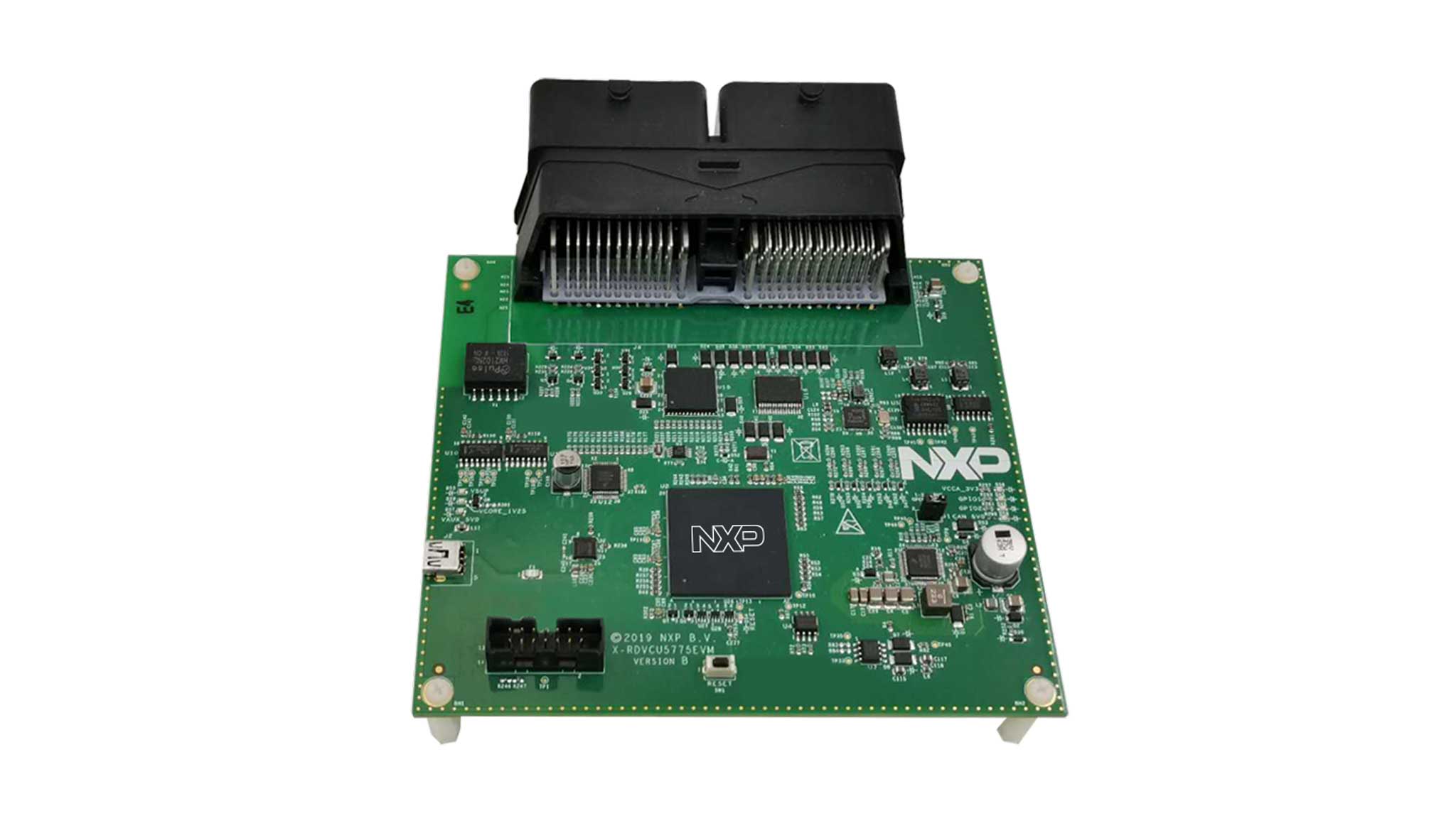
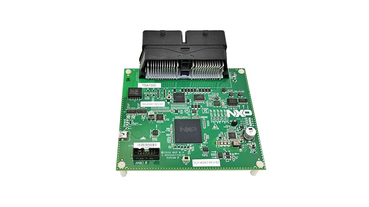
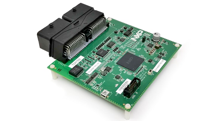
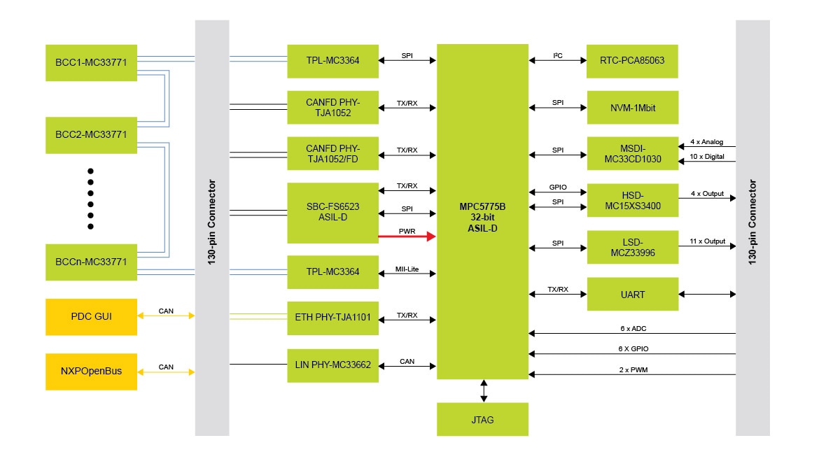
MPC5775B BMS和VCU参考设计

RDVCU5775EVM

滚动图片以放大

产品详情

选择区域:

框图

MPC5775B BMS和VCU参考设计 - 结构框图

MPC5775B BMS and VCU reference design - Block Diagram

Features

General

  • RDVCU5775EVM Features
  • target application
  • Combining BMS and VCU functions in one ECU
  • Supports dual TPL communication with daisy chain of BCC devices
  • Supports multiple input/output interfaces: MSDI, ADC, GPIO, LSD and HSD
  • Supports multiple communication interfaces: ETH, CAN(FD), LIN and UART
  • Provides two demo application projects for S32SDK and AUTOSAR MCAL
  • GUI tool is provided to easily monitor the system via CAN
  • Provide boot loader based on CAN protocol and UDS.
  • MPC5775B microcontroller (416 MAPBGA soldered)
  • MC33FS6523CAE System Basis Chip (SBC) for on-board power and a CAN physical layer
  • MC33664 Isolated Transceiver Supports Daisy Chaining of BCC Devices MC33771 Communication
  • 1 100BASE-T1 automotive Ethernet interface TJA1101
  • 3 CAN interfaces: two are supported by the TJA1052 and TJA1145 CAN FD transceivers and the other is supported by the SBC.
  • 1 LIN interface MC33662BLEF
  • PCA85063A Automotive Tiny Real Time Clock/Calendar with Alarm and I²C Bus
  • 1Mbit Automotive External EEPROM with SPI Interface
  • Standard 14-pin JTAG debug connector
  • 12 V external DC power supply required
  • Main power regulation status LED + 2 user LEDs connected to GPIO for testing
  • 电池管理系统(BMS)
  • 汽车控制单元 (VCU)
  • 汽车动力控制器
  • 混合动力和电动汽车动力

购买选项

  • CNY3,016.65
  • 数量为 1
    • 供货情况: 有货
    • 库存: 6
    • 运单: 正常情况下 1-2个工作日内发货
从恩智浦处购买从分销商处购买

文档

快速参考 文档类别.

1-5 / 10 文件

展开

设计资源

选择区域:

设计文件

4 设计文件

软件

1-5 / 8 软件文件

展开

注意: 推荐在电脑端下载软件,体验更佳。

培训

1 培训

支持

您需要什么帮助?